
Water-air combined passive feed water cooling apparatus and system

a cooling apparatus and water-air technology, applied in the direction of nuclear engineering, greenhouse gas reduction, nuclear elements, etc., can solve the problems of limited general passive auxiliary feed water cooling system for light-water nuclear reactors, possible failure of auxiliary feed water systems using pumps, etc., and achieve the effect of prolonging the exhaustion time of cooling water

Active Publication Date: 2015-08-27
KOREA ATOMIC ENERGY RES INST
View PDF3 Cites 8 Cited by
  • Summary
  • Abstract
  • Description
  • Claims
  • Application Information

AI Technical Summary

Benefits of technology

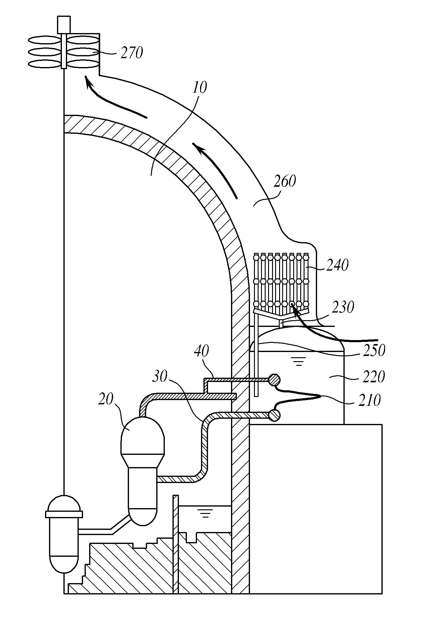
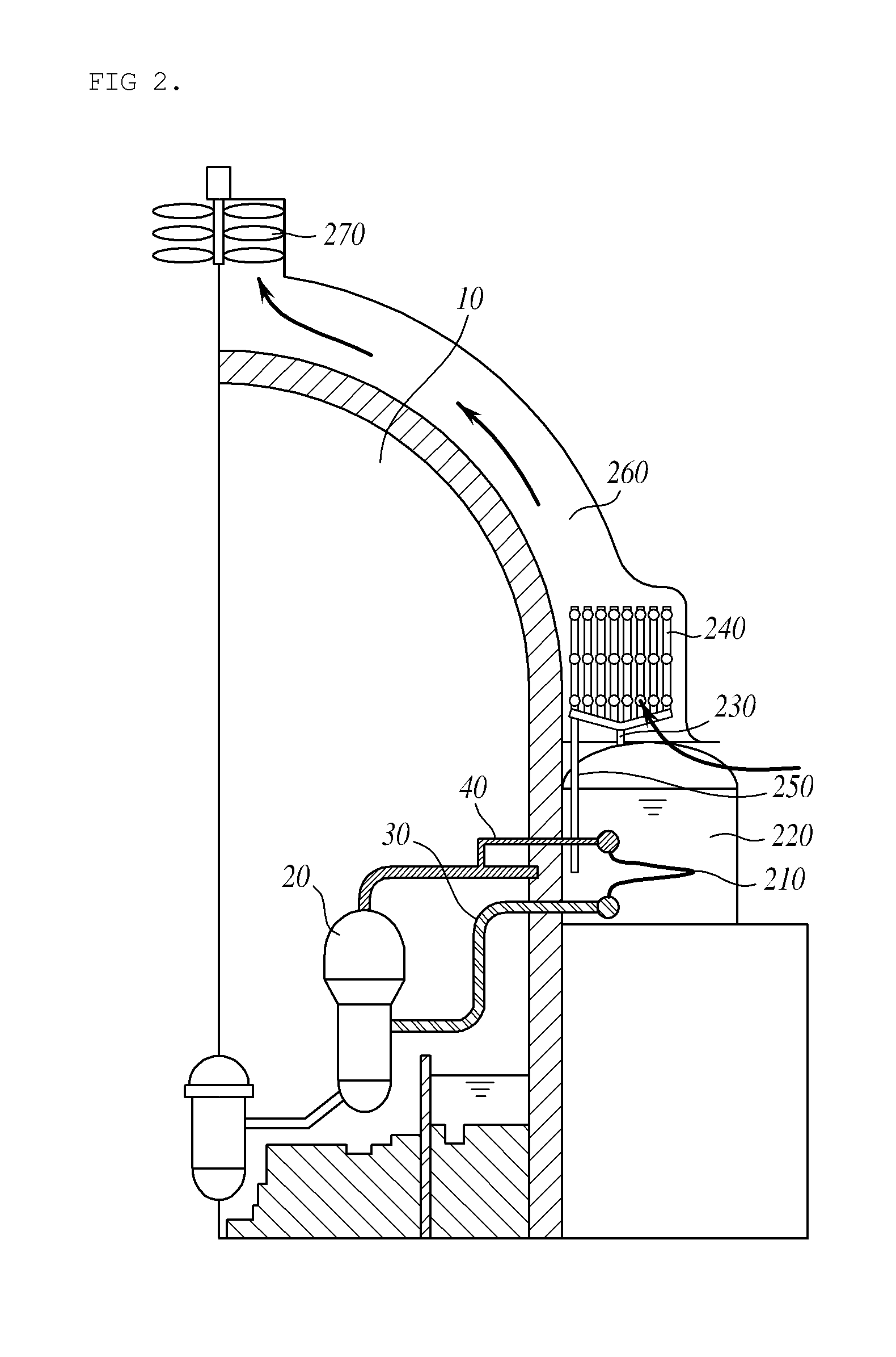
The present invention provides a cooling system for a passive feed water system that combines water and air cooling. By using an air cooling heat exchanger, the system extends the time it takes to cool down steam that is evaporated from the cooling tank. The horizontal heat exchange condensing tube is designed with a cooling fin to improve heat emission efficiency. This invention helps to keep the system cool for longer periods of time.

Problems solved by technology

However, after Fukushima nuclear accidents, it is necessary for a nuclear reactor cooling system to have about 72 hour cooling ability.
Also, an auxiliary feed water system using a pump has a possibility of a failure caused by an error of an operator, power failure, the malfunction of the pump.
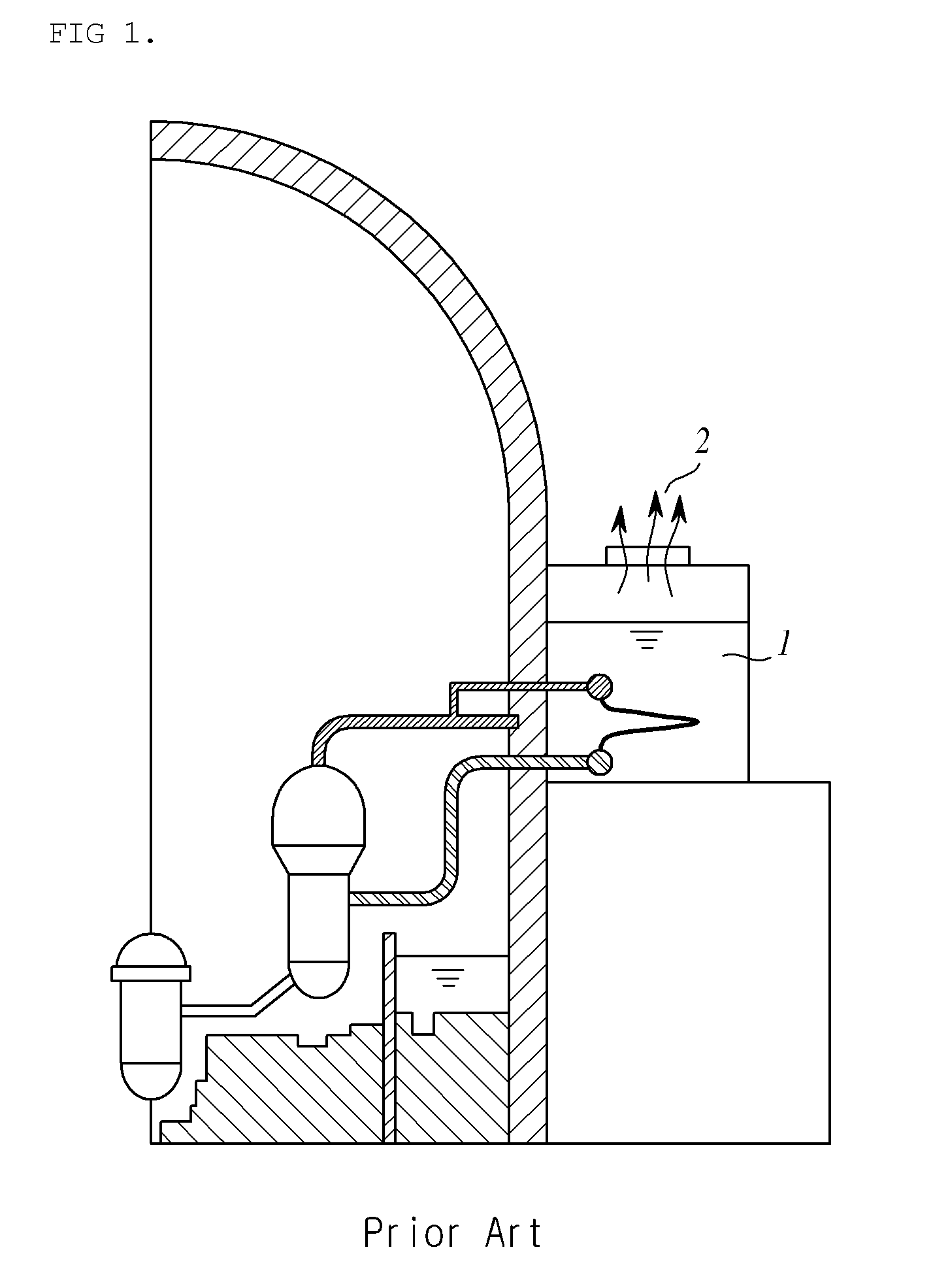
However, general passive auxiliary feed water cooling systems for a light-water nuclear reactor have limitations such as refilling a cooling water tank of a passive auxiliary feed water system with cooling water after all cooling water of the heat exchange cooling tank (PCCT) 1 is evaporated or designing a cooling water tank to be greater several times.
Due to the limitations, it is necessary to provide a water-air combined feed water cooling system extending a cooling water exhaustion time by refilling a cooling tank of a passive feed water system with steam evaporated from the cooling tank and discharged into the air.

Method used


Image

  • Water-air combined passive feed water cooling apparatus and system
  • Water-air combined passive feed water cooling apparatus and system
  • Water-air combined passive feed water cooling apparatus and system

Examples


Embodiment Construction

[0047]Hereinafter, exemplary embodiments of the present invention will be described in detail with reference to the attached drawings. Herein, configurations and operations illustrated in the drawings and described with reference thereto are just at least one embodiment. However, the technical scope and essential configurations and operations of the present invention are not limited thereto.

[0048]Generic terms widely used for functions in present are selected as the terms used herein. However, they may vary with the intension of those skilled in the art, practice, or the appearance of novel technology. Also, particularly, there are present terms selected arbitrarily by applicant(s). In this case, meanings thereof will be described in detail. Accordingly, the terms used herein are not determined simple designations but will be defined based on meanings thereof and the contents throughout the present specification.

[0049]The present invention provides a passive feed water cooling syste...


PUM


Abstract

Disclosed herein is a water-air combined passive feed water cooling apparatus including a water cooling heat exchanger connected to the inside of a containment building to cool down heat of a steam generator using a water cooling method, a cooling tank including the water cooling heat exchanger therein and storing cooling water condensing main steam generated by the steam generator, an evaporative steam pipe connected to the cooling tank, the evaporative steam pipe, into which steam of the cooling water generated by the water cooling heat exchanger in the cooling tank flows, an air cooling heat exchanger connected to the evaporative steam pipe and cooling down and liquefying the steam flowing into the evaporative steam pipe, and a condensed water collecting pipe for refilling the cooling tank with the steam liquefied by the air cooling heat exchanger.

Description

CROSS-REFERENCES TO RELATED APPLICATION[0001]This patent application claims the benefit of priority under 35 U.S.C. §119 from Korean Patent Application No. 10-2014-0023605 filed Feb. 27, 2014, the contents of which are incorporated herein by reference.BACKGROUND OF THE INVENTION[0002]1. Field of the Invention[0003]The present disclosure relates to a water-air combined passive feed water cooling apparatus and system, and more particularly, to a water-air combined passive feed water cooling apparatus and system for effective cooling, condensing steam of cooling water generated by water cooling through air cooling and refilling the same as cooling water for a heat exchanger of a passive feed water cooling system.[0004]2. Description of the Related Art[0005]After an accident of a light water reactor including a security system configured as an active pump driven using electricity, when a feed water system does not operate, residual heat of a nuclear reactor is removed by driving an auxi...

Claims


Application Information

Patent Timeline
IPC IPC(8): G21C15/18
CPCG21C15/18G21D3/06G21C15/185Y02E30/00Y02E30/30
Inventor KWON, TAE-SOONKIM, KIHWANPARK, HYUN SIKBAE, SUNG WONPARK, YUSUN
Owner KOREA ATOMIC ENERGY RES INST
Learn More