Eureka AIR delivers breakthrough ideas for toughest innovation challenges, trusted by R&D personnel around the world.

Porous polytetrafluoroethylene membrane, method for producing the same, gas-permeable membrane and ventilation member using the same

a technology of porous polytetrafluoroethylene and gas-permeable membrane, which is applied in the direction of metal layered products, synthetic resin layered products, domestic applications, etc., can solve the problems of difficulty in forming a waterproof structure while ensuring audio functions, and the entry of liquids with a low surface tension cannot be fully prevented, so as to reduce wrinkles and sagging

Active Publication Date: 2015-08-27
NITTO DENKO CORP
View PDF9 Cites 15 Cited by
  • Summary
  • Abstract
  • Description
  • Claims
  • Application Information

AI Technical Summary

Benefits of technology

The invention provides a porous PTFE membrane with good liquid repellency, which can meet practical requirements. Additionally, it reduces wrinkling and sagging during cutting and integration into a housing.

Problems solved by technology

Since sound needs to be transmitted through these openings, which makes it difficult to form a waterproof structure while ensuring the audio functions.
Even if a highly water-repellent porous PTFE membrane is used as a gas-permeable membrane, entry of a liquid with a low surface tension cannot be fully prevented.

Method used

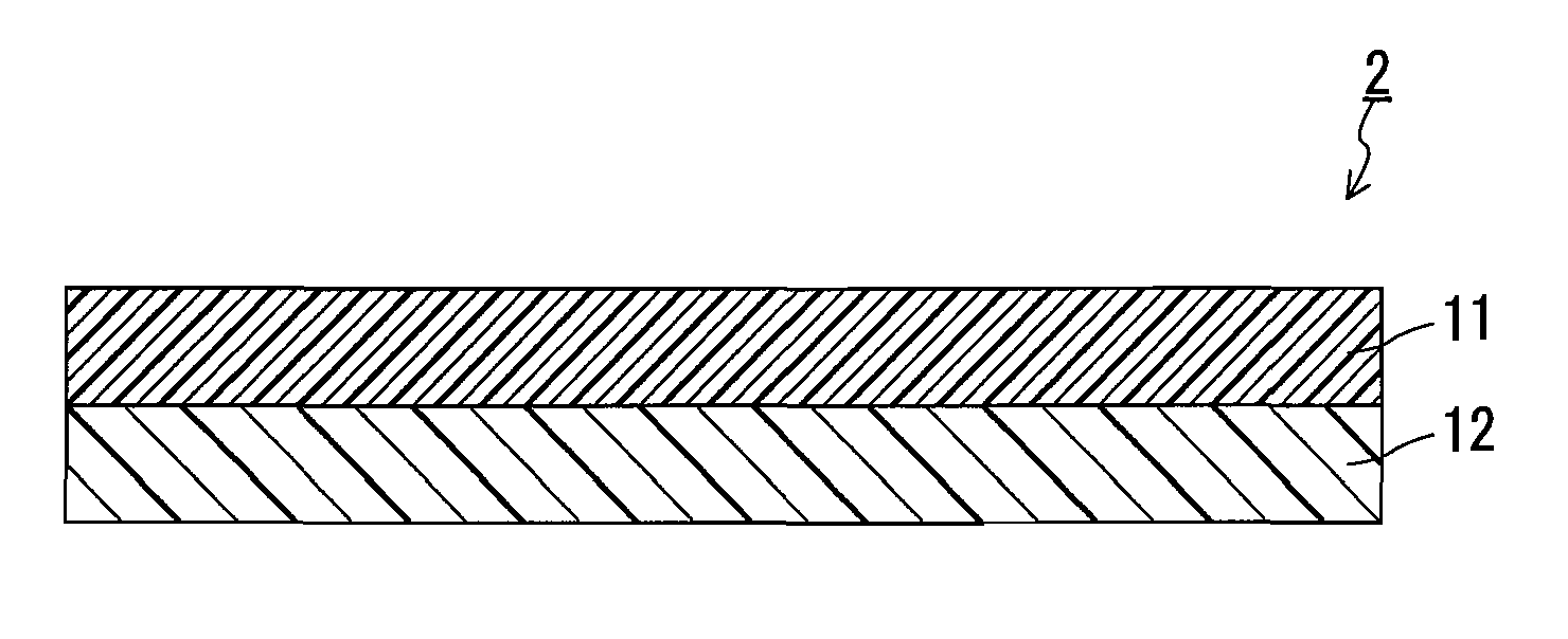
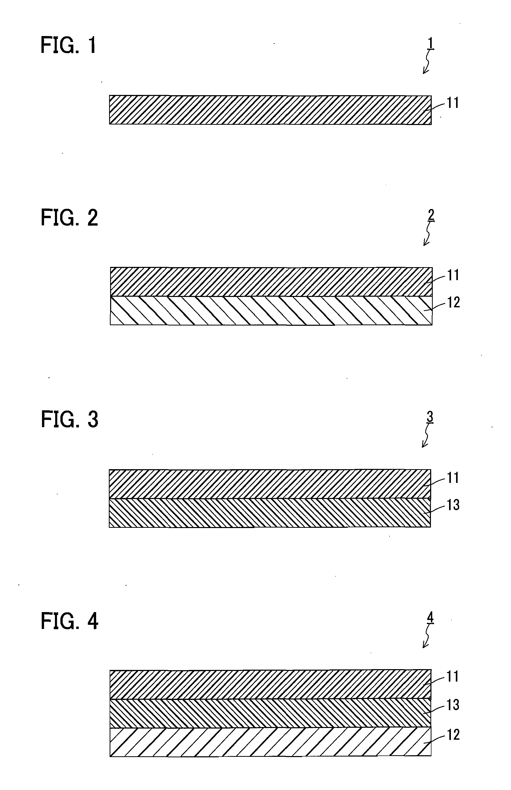

Image

  • Porous polytetrafluoroethylene membrane, method for producing the same, gas-permeable membrane and ventilation member using the same
  • Porous polytetrafluoroethylene membrane, method for producing the same, gas-permeable membrane and ventilation member using the same
  • Porous polytetrafluoroethylene membrane, method for producing the same, gas-permeable membrane and ventilation member using the same

Examples


example 1

[0075]An amount of 100 parts by weight of a PTFE fine powder (F 104 manufactured by DAIKIN INDUSTRIES, LTD.) and 20 parts by weight of n-dodecane (manufactured by Japan Energy Corporation) serving as a forming aid were uniformly mixed. The obtained mixture was compressed using a cylinder, and then formed into a sheet-shaped mixture by ram extrusion. Next, the sheet-shaped mixture obtained was rolled to a thickness of 0.2 mm by passing the mixture through a pair of metal rolls. Furthermore, the mixture was dried by heating at 150° C. to remove the forming aid, and thus a sheet-shaped body of PTFE was obtained. Next, the sheet-shaped body obtained was stretched in the longitudinal direction (rolling direction) at a stretching temperature of 260° C. and at a stretching ratio of 10.

[0076]Next, the porous PTFE membrane fabricated as described above was immersed for several seconds in a dye solution obtained by mixing 20 parts by weight of a black dye (SP BLACK 91-L manufactured by ORIENT...

example 2

[0079]A liquid-repellent porous PTFE membrane subjected to liquid-repellent treatment (Example 2) was obtained in the same manner as in Example 1, except that the stretching ratio in the width direction was 15. The surface density of the liquid-repellent porous PTFE membrane of Example 2 was 4 g / m2. The elongation at break, sound pressure loss, gas permeability, waterproofness, and liquid repellency thereof are as shown in Table 1. The occurrences of wrinkling and sagging of the membrane during cutting, integration, and removal are as shown in Table 2.

example 3

[0080]A liquid-repellent porous PTFE membrane subjected to liquid-repellent treatment (Example 3) was obtained in the same manner as in Example 1, except that the stretching ratio in the width direction was 7. The surface density of the liquid-repellent porous PTFE membrane of Example 3 was 8.6 g / m2. The elongation at break, sound pressure loss, gas permeability, waterproofness, and liquid repellency thereof are as shown in Table 1. The occurrences of wrinkling and sagging of the membrane during cutting, integration, and removal are as shown in Table 2.


PUM

PropertyMeasurementUnit
elongation at breakaaaaaaaaaa
pore diameteraaaaaaaaaa

Abstract

The present invention provides a porous polytetrafluoroethylene membrane having a surface coated with a liquid-repellent agent. In this porous polytetrafluoroethylene membrane, the liquid-repellent agent is a polymer obtained by polymerization of monomers consisting essentially of CH2=CHCOOCH2CH2C6F13. This porous polytetrafluoroethylene membrane is suitable for use as a gas-permeable membrane that allows passage of gases but prevents entry of liquids and / or dust, specifically as a waterproof sound-transmitting membrane, a waterproof gas-permeable membrane, or a dustproof gas-permeable membrane.

Description

TECHNICAL FIELD[0001]The present invention relates to a porous polytetrafluoroethylene membrane imparted with liquid repellency and a method for producing the same. The present invention also relates to a gas-permeable membrane and a ventilation member each using this porous membrane.BACKGROUND ART[0002]In recent years, it has been common for electronic devices, such as mobile phones, laptop computers, electronic notebooks, digital cameras, and gaming machines, to have audio functions. These devices are required to have a waterproof structure. A housing of an electronic device with audio functions is usually provided with openings located at positions corresponding to a sound emitter and a sound receiver such as a speaker, a microphone, and a buzzer. Since sound needs to be transmitted through these openings, which makes it difficult to form a waterproof structure while ensuring the audio functions. It has been attempted to ensure both sound transmission through an opening of a hous...

Claims


Application Information

Patent Timeline
Patent Type & Authority Applications(United States)
IPC IPC(8): B01D67/00B01D69/06B01D71/36
CPCB01D67/0088B01D71/36B01D69/06B01D2325/38B01D2323/04B01D2325/24B01D67/0027C08J2327/18C08J2433/16B32B5/022B32B5/024B32B5/16B32B15/08B32B27/08B32B27/12B32B27/14B32B27/281B32B27/32B32B27/322B32B27/34B32B27/36B32B2255/26B32B2264/0257B32B2307/724B32B2307/7265B32B2457/00C08J7/0427B01D69/1213B01D69/10B29C55/14
Inventor MORI, MASAAKIIKEYAMA, YOSHIKI
Owner NITTO DENKO CORP
Why Eureka
Eureka Blog
Learn More