Eureka AIR delivers breakthrough ideas for toughest innovation challenges, trusted by R&D personnel around the world.

Overflow Downdraw Glass Forming Method and Apparatus

a technology of glass forming and downdrawing, which is applied in the direction of glass rolling apparatus, glass tempering apparatus, manufacturing tools, etc., can solve the problems of fewer square feet of production, increased shortening and adverse effect on the width of the manufactured sheet, and required process changes

Inactive Publication Date: 2007-06-28
CORNING INC
View PDF40 Cites 17 Cited by
  • Summary
  • Abstract
  • Description
  • Claims
  • Application Information

AI Technical Summary

Benefits of technology

[0016] The present invention is a significant modification of “The Overflow Process” that embodies design features that support the forming apparatus in a manner such that the deformation that results from thermal creep has a minimum effect on the thickness variation of the glass sheet.
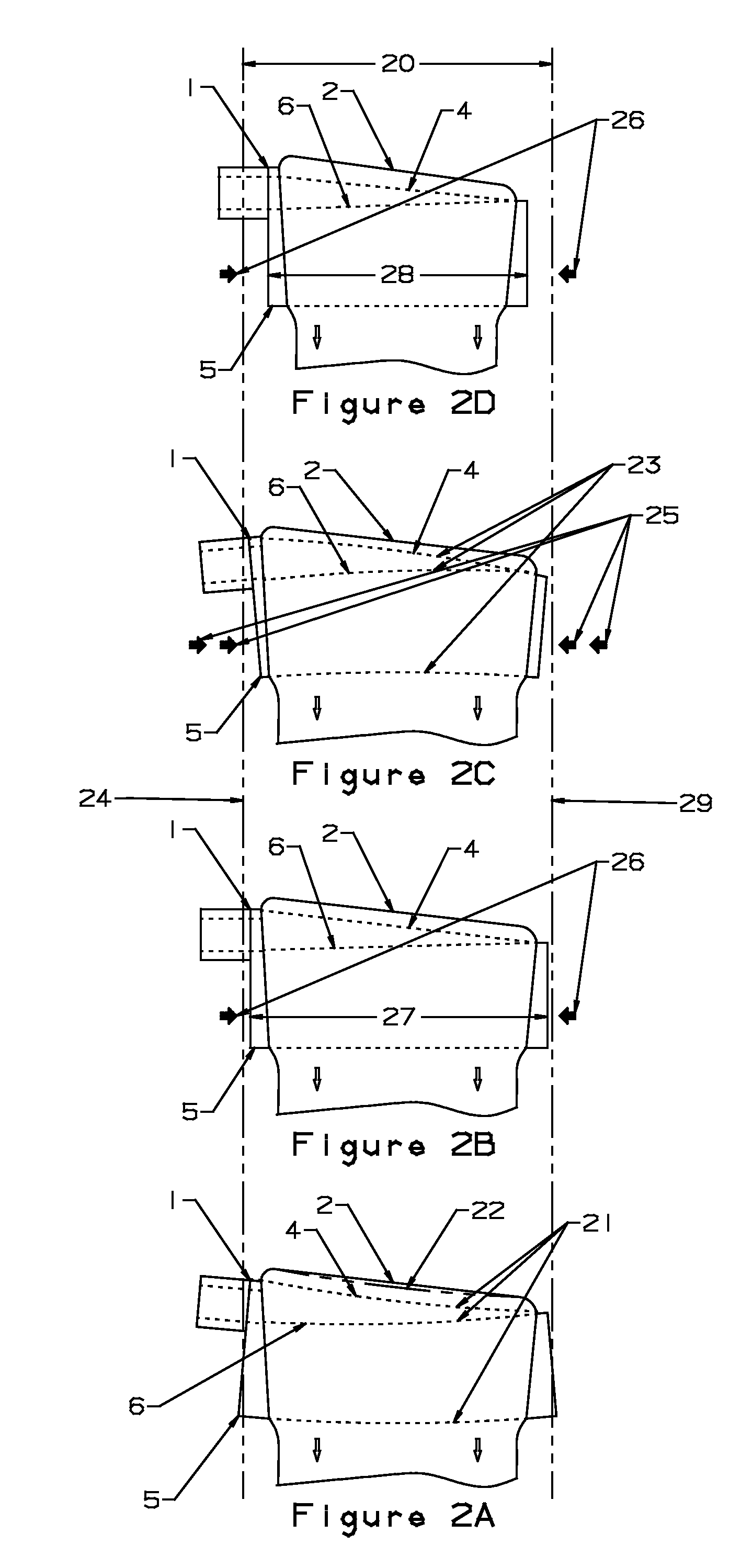
[0018] Embodiments of this invention suspend the forming structure from the top in a manner such that the thermal creep, which inevitably occurs, has a minimum impact on the glass flow characteristics of the forming structure. In these embodiments there are no externally applied compression loads on the forming structure and any moments that produce sagging of the forming structure are minimized. Thus sheet glass may be manufactured for a longer time without requiring changing of the forming structure.
[0020] Other embodiments of this invention also allow for the doubling of the length of the forming structure, thus proportionally increasing the production rate.

Problems solved by technology

This increased shortening has an adverse effect on the width of the manufactured sheet.
This results in fewer square feet of production, and required process changes.
The size capability of presently available equipment for isostatic pressing limits the dimensions of the forming structure.
A major drawback of the apparatus of “The Overflow Process” is that the forming apparatus deforms during a manufacturing campaign in a manner such that the glass sheet no longer meets the thickness and width specifications.
This is a primary cause for premature termination of the production run.
Another drawback is that the edge directors are required because the glass does not flow over the ends of the forming structure.
Another drawback of the apparatus is that the production rate is limited by the size forming structure.

Method used


Image

  • Overflow Downdraw Glass Forming Method and Apparatus
  • Overflow Downdraw Glass Forming Method and Apparatus
  • Overflow Downdraw Glass Forming Method and Apparatus

Examples


Embodiment Construction

[0076] The refractory materials from which the forming trough and its support structure are made have high strength in compression and low strength in tension. Like most structural materials they also change shape when stressed at high temperature by a process termed “Thermal Creep”. These material characteristics and how these characteristics affect the manufacturing process are the reason for this invention.

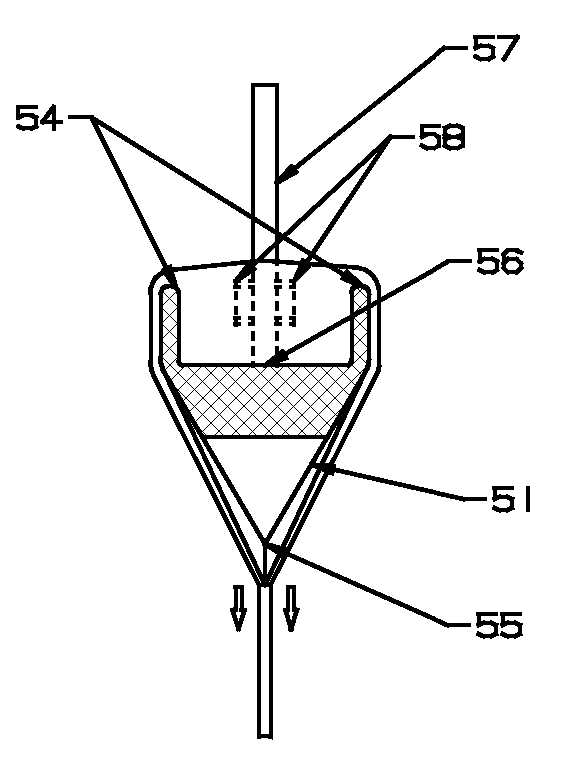
[0077]FIGS. 5A through 5D illustrate a forming structure (51) which is supported from the top at surface (59) by a center support web (57). The support web (57) is attached to the bottom (56) of the trough in the forming structure (51). For clarity of illustration the support web (57) is shown as being rectangular in cross section and having a longitudinal length less than that of the weirs (54) on the forming structure (51). In practice the longitudinal length of the support web (57) is optionally the full length of the weirs (54) and could even extend back into the inflow pi...


PUM

PropertyMeasurementUnit
angleaaaaaaaaaa
temperaturesaaaaaaaaaa

Abstract

The present invention discloses improved apparatuses for forming sheet glass. In one embodiment, the invention introduces a structural web that supports the forming structure in a manner such that the thermal creep which inevitably occurs has a minimum impact on the glass flow characteristics of the forming structure.

Description

REFERENCE TO RELATED APPLICATIONS [0001] This application claims an invention which was disclosed in Provisional Application No. 60 / 754,106, filed Dec. 27, 2005, entitled “OVERFLOW DOWNDRAW GLASS FORMING METHOD AND APPARATUS”. The benefit under 35 USC §119(e) of the U.S. provisional application is hereby claimed, and the aforementioned application is hereby incorporated herein by reference.BACKGROUND OF THE INVENTION [0002] This invention relates generally to the manufacture of glass sheet and, more particularly, to glass sheet used for the production of TFT / LCD display devices that are widely used for computer displays and for flat panel television. DESCRIPTION OF RELATED ART [0003] The glass that is used for semiconductor powered display applications must have very high surface quality to allow the successful application of semiconductor type material. Sheet glass made using the apparatus of U.S. Pat. No. 3,338,696 assigned to Corning, Inc. makes the highest quality glass as forme...

Claims


Application Information

Patent Timeline
Patent Type & Authority Applications(United States)
IPC IPC(8): C03B13/00C03B15/00C03B17/00
CPCC03B17/064
Inventor PITBLADDO, RICHARD B.
Owner CORNING INC
Why Eureka
Eureka Blog
Learn More