Planetary mixer

Active Publication Date: 2015-08-20
INOUE SEISAKUSHO MFG
View PDF1 Cites 5 Cited by
  • Summary
  • Abstract
  • Description
  • Claims
  • Application Information

AI Technical Summary

Benefits of technology

The present invention is a planetary mixer with improved efficiency and economics for mixing and kneading materials in tank. The technical effects of the mixer include adjusting the width of the frame-shaped stirring blades to allow secure and efficient flow of materials in the tank, adjusting the edge angle and slant angle of the stirring blades for high-viscosity or semisolid state mixing / kneading, and adjusting the width between the inward front ends of the slope faces for efficient mixing and dilution with minimal contamination. These technical effects provide improved mixing and kneading performance and reduced operating time and costs.

Problems solved by technology

This scraping operation is accompanied with dangers.
If such scraping operation is not conducted, it becomes difficult to conduct homogeneous treatment.
Particularly in a case of a treatment process including a step where the materials are subjected to strong kneading and then dilution, blob and lump are likely formed and the incorporation of lump, etc. during the dilution may cause failure of quality.
Further, since such scraping operation is necessarily conducted halfway in the operation, the operation cannot be carried out continuously.
Furthermore, since the tank cannot be tightly closed until completion of the scraping operation, in a case where a volatile organic solvent is used, problems of environmental pollution may sometimes be caused by diffusion of the solvent.

Method used


Image

  • Planetary mixer
  • Planetary mixer
  • Planetary mixer

Examples


Embodiment Construction

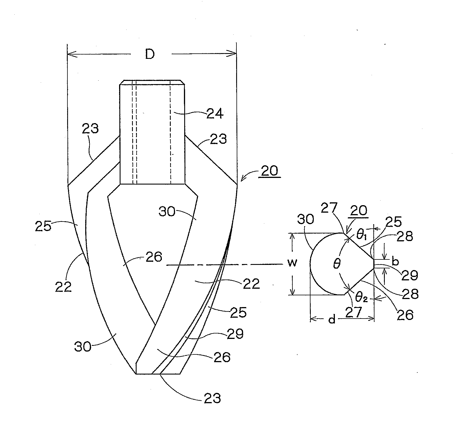
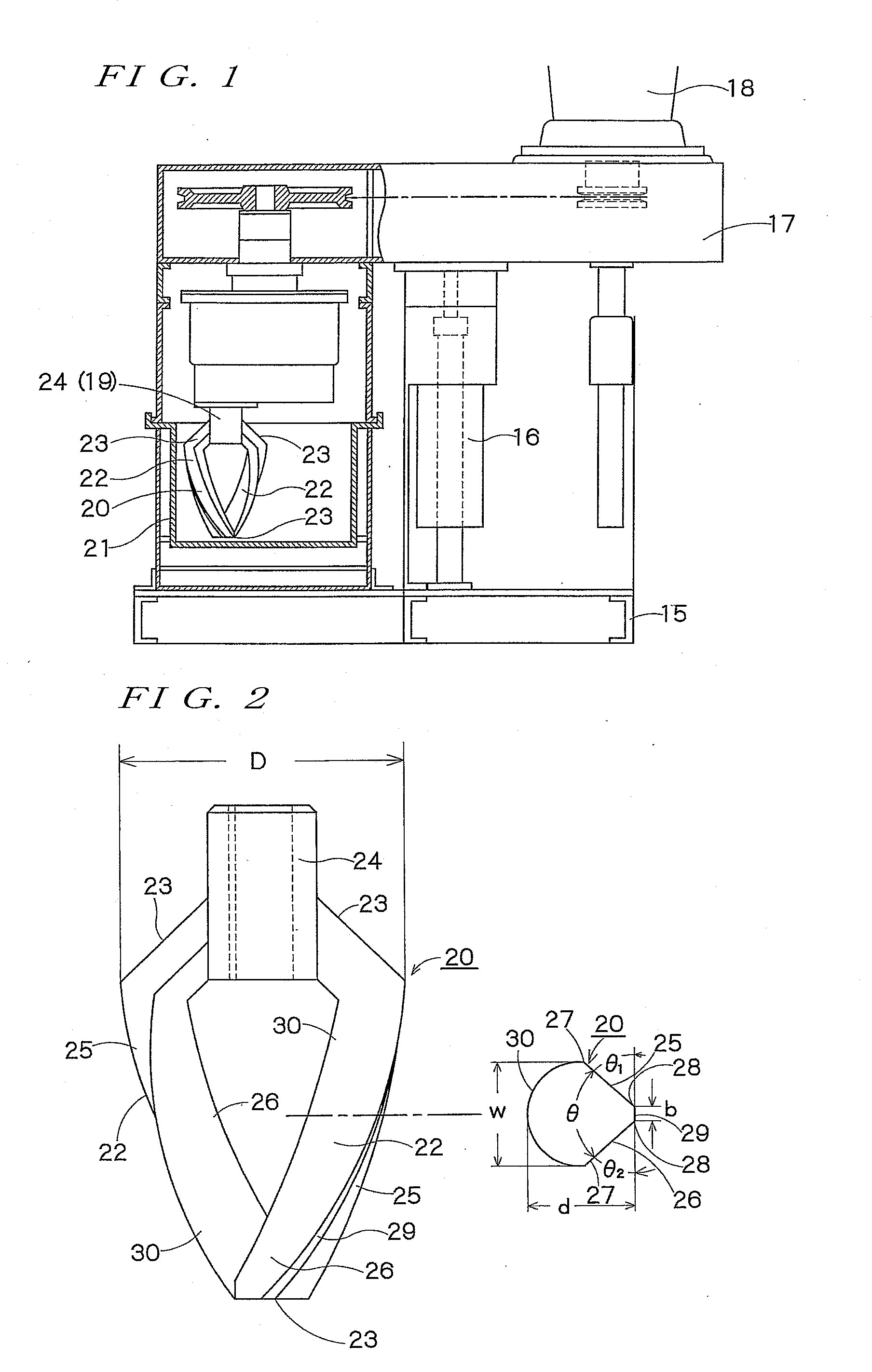
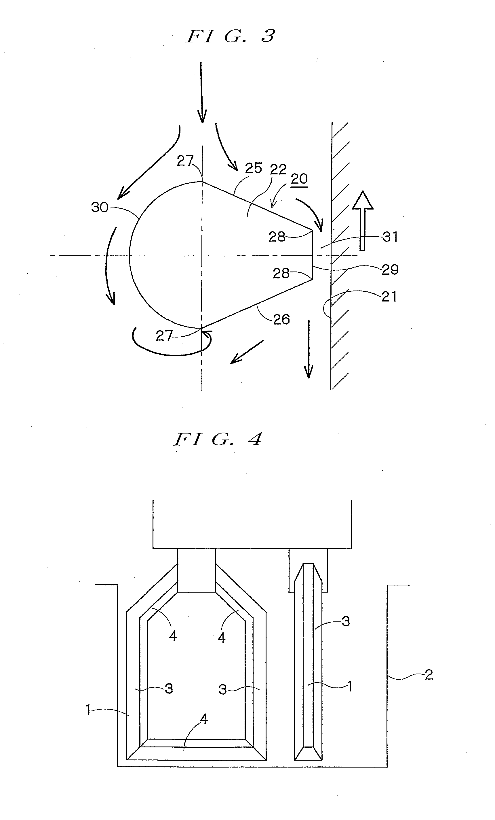
[0026]The planetary mixer of the present invention may be used for production steps of various products in the fields of chemistry, medicines, electronics, ceramics, foods, feed, etc. A main body 15 of the planetary mixer has a stirring head 17 which moves upward and downward by a lifting cylinder 16. A plurality of stirring shafts 19 perform revolution and rotation via a driving means such as a driving motor 18 disposed above the stirring head 17, by which a frame-shaped stirring vane (a frame-shaped blade) 20 disposed at the lower end of the stirring shaft performs planetary motion in a tank (vessel or stirring tank) 21 in its entirety. The frame-shaped stirring blade 20 is formed into a substantially rectangular frame shape, having a vertical side portion 22 and a horizontal side portion 23. The frame-shaped stirring blade may be a frame-shaped stirring blade as shown in FIG. 4 of which the horizontal side portion located at the upper side and the horizontal side portion located ...


PUM

PropertyMeasurementUnit
Angleaaaaaaaaaa
Angleaaaaaaaaaa
Fractionaaaaaaaaaa

Abstract

A planetary mixer which is used for production steps of various products in chemistry, medical treatment, electronics, ceramics, medicines, foods, feed and the like, and in which flame-shaped stirring blades are allowed to perform planetary motion in a tank, by which solid / liquid type treatment materials are subjected to stirring, blending, mixing / kneading, kneading or the like and it is intended to prevent adhesion of materials to a vertical side portion of the flame-shaped stirring blades.The vertical side portion 22 of the frame-shaped stirring blades 20 is constituted to have a cross-sectional configuration which has two slope faces 25, 26 slanting toward an inner wall of the tank, an edge face 29 connecting outward front ends 28 of the slope faces, and an arcuate inner face 30 connecting inward front ends 27 of the slope faces. The inward front ends are located far apart from the inner wall of the tank and the outward front ends are located near the inner wall of the tank, in which the distance between the inward front ends is broad and the distance between the outward front ends is narrow. Since the inner face 30 of the vertical side portion is formed into an arcuate configuration, the materials can flow without backwater, and adhesion and fixing thereof can be prevented.

Description

FIELD OF THE INVENTION[0001]The present invention relates to a planetary mixer which is used for various fields such as chemistry, medicines, electronics, ceramics, foods and feed, and in which stirring vanes formed into a frame shape (a flame-shaped blade) perform planetary motion in a tank (a vessel or a stirring tank), by which solid / liquid type treatment materials can be subjected to a treatment such as stirring, blending, mixing / kneading or kneading.BACKGROUND INFORMATION[0002]Treatment operations such as stirring, blending, mixing / kneading or kneading of solid / liquid type treatment materials of from a low viscosity to a high viscosity (up to 3,000 Pa·s) regardless of oiliness or aqueousness, have been mainly made in a batch system by a planetary mixer, for example, a bi-axial mixer (such as a mixer having two frame-shaped stirring blades), a tri-axial mixer (such as a mixer having three frame-shaped stirring blades, or a mixer having two frame-shaped stirring blades and one tu...

Claims


Application Information

Patent Timeline
IPC IPC(8): B01F7/30B01F3/12B01F7/00
CPCB01F7/30B01F2215/0036B01F3/1271B01F7/003B01F2215/0422B01F27/806B01F27/96B01F27/95B01F27/80B01F23/59B01F27/2324B01F27/11251B01F2101/2204A47J43/0711
Inventor INOUE, MASAKAZUNAGAI, SEIJIKAWAHARA, TOMOHARU
Owner INOUE SEISAKUSHO MFG
Why Eureka
Try Eureka