
Panel laminating method, panel assembly and electronic device

a technology of laminating method and panel, applied in the direction of electrical apparatus casing/cabinet/drawer, coupling device connection, paper/cardboard container, etc., can solve the problem of unfavorable narrowing of the border of the handheld touch device, uncured transparent adhesive layer may overflow out of the dam, etc. problem, to achieve the effect of simplifying the complexity of manufactur

Active Publication Date: 2015-08-13
HTC CORP
View PDF8 Cites 11 Cited by
  • Summary
  • Abstract
  • Description
  • Claims
  • Application Information

AI Technical Summary

Benefits of technology

The patent is about a new method for laminating panels that simplifies the manufacturing process. The method uses UV light to decrease the flowability of the adhesive, allowing for the elimination of a conventional dam to prevent the adhesive from spreading. This not only reduces complexity but also allows for a narrower border design.

Problems solved by technology

However, the material of the dam has to employ a liquid optical clear adhesive with high viscosity which is not easy to deaerate and to coat, thereby increasing the complexity of manufacture.
In addition, the dam has to be disposed between the periphery of the display panel and the active display area of the display panel, such that it is unfavourable to narrow the border of the handheld touch device.
Furthermore, the flowability of the transparent adhesive layer remains before curing, so that the un-cured transparent adhesive layer may overflow out of the dam due to any movement or sway.
As such, additional cleaning procedures are required, resulting in difficulties on the automated production.

Method used


Image

  • Panel laminating method, panel assembly and electronic device
  • Panel laminating method, panel assembly and electronic device
  • Panel laminating method, panel assembly and electronic device

Examples


Embodiment Construction

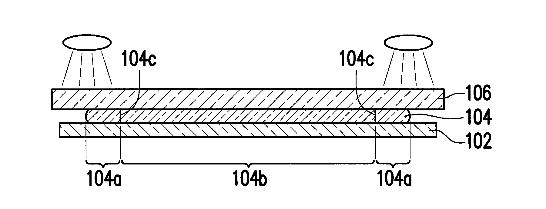
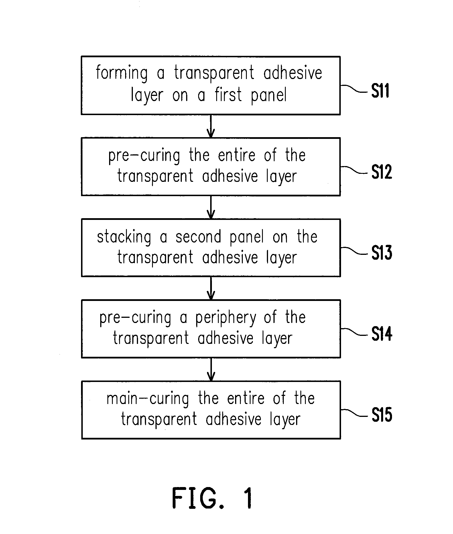
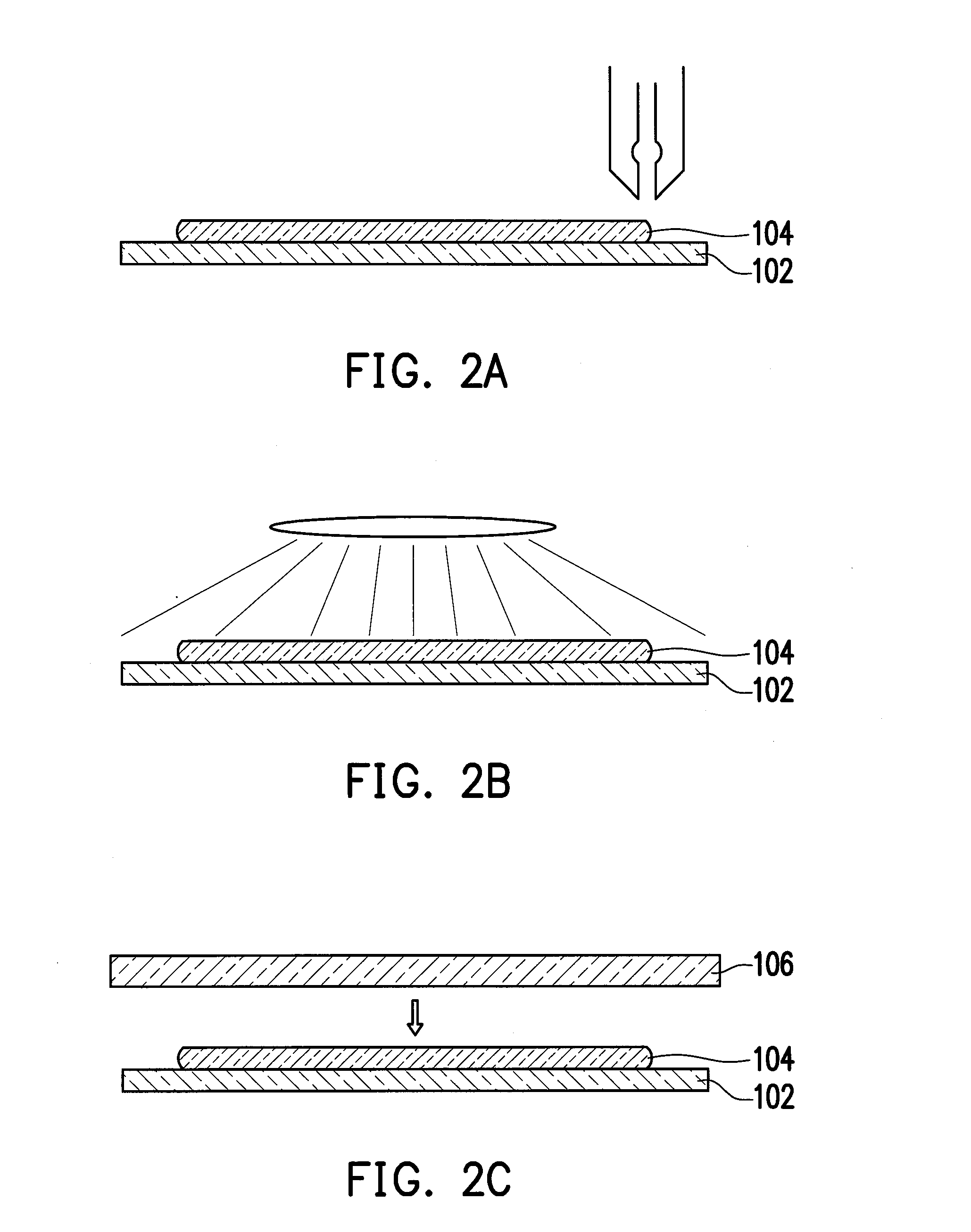
[0019]FIG. 1 is a flowchart illustrating a panel laminating method according to an embodiment of the application. FIG. 2A through FIG. 2E are cross-sectional views sequentially illustrating steps of the panel laminating method depicted in FIG. 1. Referring to FIG. 1 and FIG. 2A, Step S11 is performed, a transparent adhesive layer 104 is formed on a first panel 102. In Step S11, a liquid optical clear adhesive (LOCA) may be coated on the first panel 102 to form the transparent adhesive layer 104, as shown in FIG. 2A.

[0020]Referring to FIG. 1 and FIG. 2B, Step S12 is performed after the transparent adhesive layer 104 is formed. In Step S12, the entire of the transparent adhesive layer 104 is immediately pre-cured, as shown in FIG. 2B, so as to increase the viscosity of the transparent adhesive layer 104, which implies the flowability of the transparent adhesive layer 104 may be decreased. Here, the pre-curing process employs ultraviolet light with a relatively low dose to irradiate. S...


PUM

PropertyMeasurementUnit
transparentaaaaaaaaaa
viscosityaaaaaaaaaa
areaaaaaaaaaaa

Abstract

A panel laminating method is provided with the following steps. A transparent adhesive layer is formed on a first panel. At least a portion of the transparent adhesive layer is pre-cured to increase the viscosity of the transparent adhesive layer. After the transparent adhesive layer is pre-cured, a second panel is stacked on the transparent adhesive layer. After the second panel is stacked on the transparent adhesive layer, the entire of the transparent adhesive layer is main-cured so that the second panel is laminated to the first panel through the transparent adhesive layer. Besides, a panel assembly and an electronic device are also provided.

Description

BACKGROUND OF THE INVENTION[0001]1. Field of the Invention[0002]The application relates to a panel laminating method, and more particularly, to a method for laminating two panels with each other and a panel assembly using the same.[0003]2. Description of Related Art[0004]Since handheld touch devices, such as smart phones and tablet computers, have characteristics of multiple functions and convenience to carry, etc., this kind of handheld devices has become relatively popular to consumers. The handheld touch devices are usually equipped with a display panel to display an image and equipped with a touch panel on the display panel, so as to input commands in corporation with the image displayed by the display panel.[0005]Conventionally, in order to laminate the touch panel onto the display panel, a dam is firstly formed on the display panel to define distribution regions of liquid optical clear adhesive (LOCA). Subsequently, the liquid optical clear adhesive is coated on the area surro...

Claims


Application Information

Patent Timeline
Patent Type & Authority Applications(United States)
IPC IPC(8): H05K7/14B32B38/00B32B37/12B32B7/12B32B37/24
CPCH05K7/1427B32B7/12B32B37/24B32B37/1284B32B2307/412B32B2250/02B32B2457/202B32B2457/208B32B2037/243B32B38/0008B32B2457/00B32B37/003B32B37/18B32B2037/1253B32B2310/0831Y10T428/24752Y10T156/10
Inventor LO, CHU-CHUNWU, HUNG-WEI
Owner HTC CORP
Learn More