
Semiconductor device

a technology of semiconductor devices and resistors, applied in the direction of semiconductor devices, resistors, electrical equipment, etc., can solve the problems of loss of resistance ratios, difficulty in enhancing resistance ratio accuracy, and loss of resistance ratio balance in resistor circuits

Active Publication Date: 2015-08-13
ABLIC INC
View PDF5 Cites 3 Cited by
  • Summary
  • Abstract
  • Description
  • Claims
  • Application Information

AI Technical Summary

Benefits of technology

The patent text describes a way to make semiconductor circuits that have accurate resistance elements, which are not affected by the stresses caused by metal wiring.

Problems solved by technology

As a result, the resistance values of the respective resistor groups deviate from a desired design value and a balance among the resistance ratios in the resistor circuit is lost.
Therefore, a related-art resistor circuit in which metal films are separately formed for the respective resistor groups has a problem in that enhancing the accuracy of the resistance ratios is difficult.

Method used


Image

  • Semiconductor device
  • Semiconductor device
  • Semiconductor device

Examples


Embodiment Construction

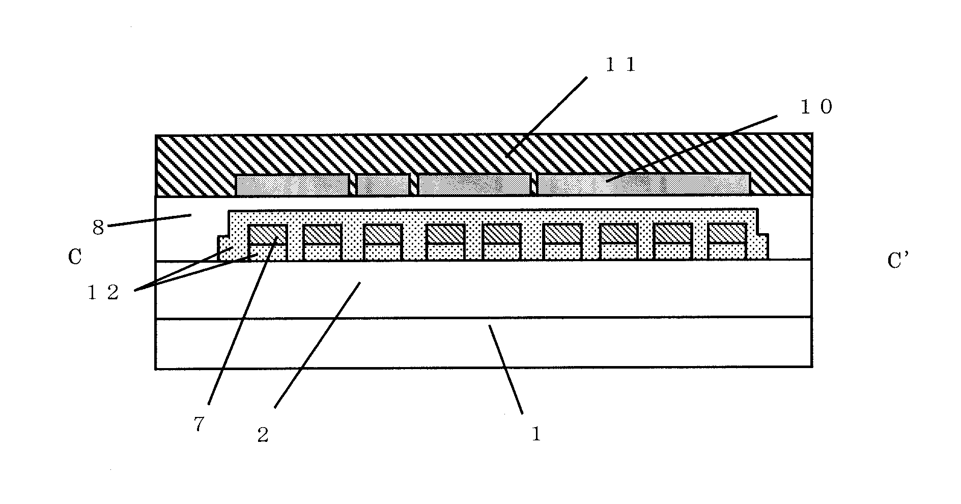
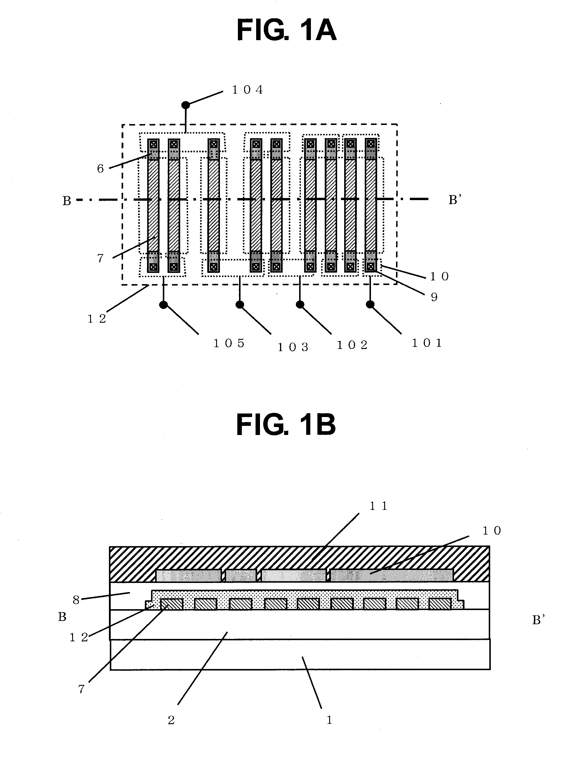
[0035]Embodiments of the present invention are described in the following with reference to the attached drawings. FIG. 1A is a plan view illustrating a resistor circuit to be a semiconductor device according to the present invention, in which resistor elements formed of polycrystalline silicon are two-dimensionally arranged, and FIG. 1B is a sectional view taken along the line B-B′ of FIG. 1A.

[0036]Electrical connection among the resistor elements forming the resistor circuit is as illustrated in a circuit diagram of FIG. 3. For example, four of the resistor elements are connected in series between a terminal 101 and a terminal 102.

[0037]As illustrated in FIG. 1B, the resistor elements forming the resistor circuit are formed of a polycrystalline silicon film that is deposited on a flat thick oxide film 2 on a semiconductor substrate 1. A high stress insulating film 12 is further deposited on the resistor elements so as to sufficiently cover upper surfaces and side surfaces of the r...


PUM


Abstract

Provided is a semiconductor resistor circuit with high accuracy. An insulating film is formed to cover a plurality of resistor groups having upper portions covered with a plurality of metal wirings. The insulating film has a membrane stress that is higher than that of the metal wirings, and is formed between the metal wirings and the resistor groups.

Description

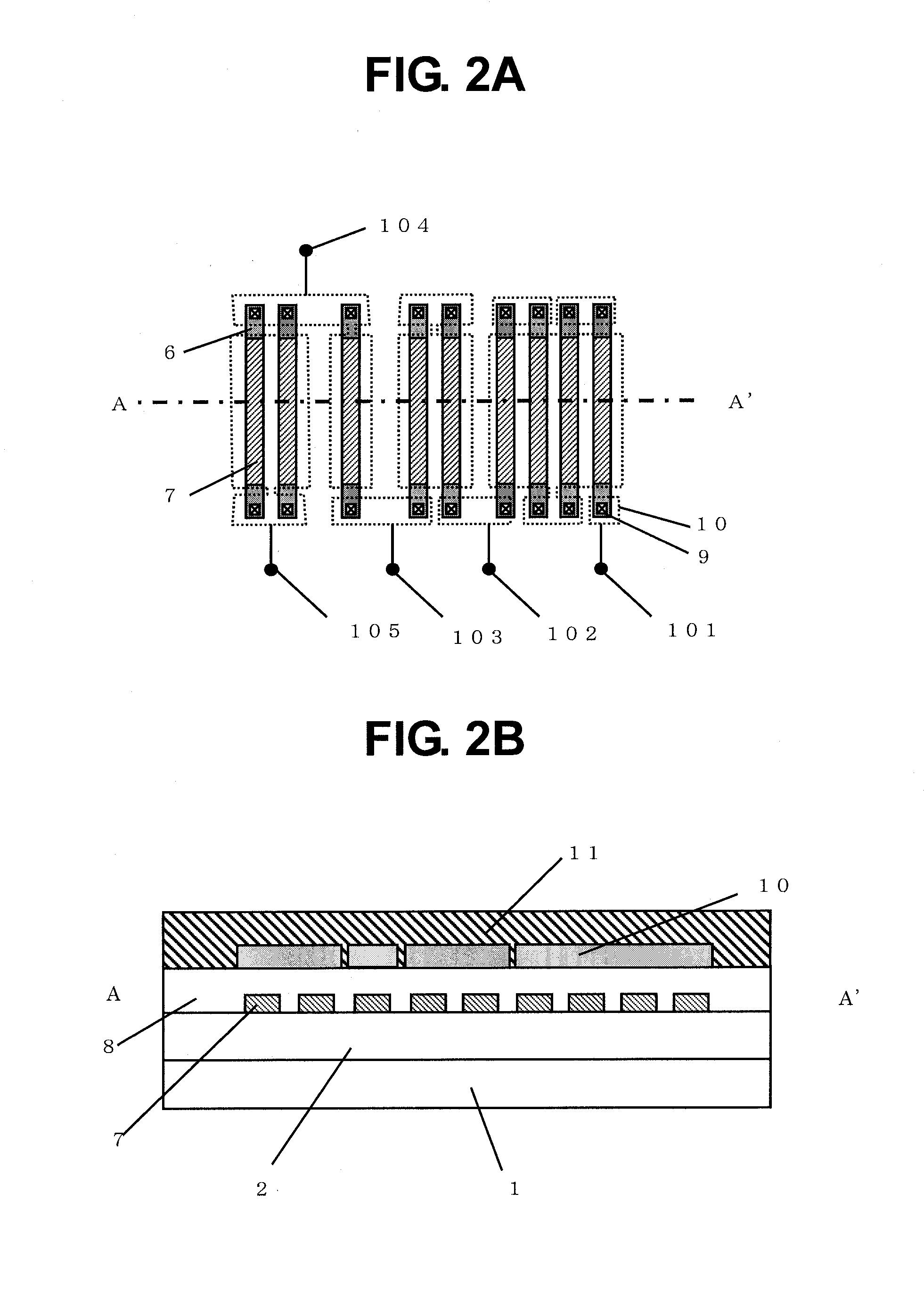
BACKGROUND OF THE INVENTION[0001]1. Field of the Invention[0002]The present invention relates to a semiconductor device. More particularly, the present invention relates to a resistor circuit to be used in a semiconductor device.[0003]2. Description of the Related Art[0004]Resistors to be used in a semiconductor device or a semiconductor integrated circuit include a diffused resistor in which impurities are implanted into a monocrystalline silicon semiconductor substrate, which have a conductive type opposite to that of the semiconductor substrate, and a polycrystalline silicon resistor formed of polycrystalline silicon having impurities implanted thereinto.[0005]FIG. 2A is a plan view illustrating a related-art resistor circuit in which resistor elements formed of polycrystalline silicon are two-dimensionally arranged. FIG. 2B is a sectional view taken along the line A-A′ of FIG. 2A.[0006]A high concentration impurity region 6 and a low concentration impurity region 7 are formed in...

Claims


Application Information

Patent Timeline
Patent Type & Authority Applications(United States)
IPC IPC(8): H01L27/10H01L49/02
CPCH01L27/101H01L28/20H01L27/0802
Inventor HARADA, HIROFUMIAKINO, MASARU
Owner ABLIC INC
Learn More