
Apparatus and method for atomic force microscopy

a technology apparatus, which is applied in the direction of scanning probe techniques, instruments, nanotechnology, etc., can solve the problems of high cost of afm measurement system under high vacuum, damage to sample surface, and inability to perform afm measurement in (ambient) air, so as to improve the performance of atomic force microscopy measurement, improve the quality of measurement, and facilitate handling

Inactive Publication Date: 2015-08-13
BRUKER NANO INC +1
View PDF16 Cites 4 Cited by
  • Summary
  • Abstract
  • Description
  • Claims
  • Application Information

AI Technical Summary

Benefits of technology

The present invention provides an atomic force microscopy measurement apparatus or method that can achieve better performance without the necessity of measuring under vacuum conditions. The apparatus or method can use a low-cost vacuum environment for the pretreatment of samples, allowing for easy handling and manipulation of samples. Additionally, separate controlled environments such as vacuum can be used for additional pretreatment processing while still achieving improved sub nanometer spatial resolution, better signal-to-noise ratio, and reduced measurement force as compared to regular air AFM measurements. The apparatus or method also provides a stable environment for sample pretreatment and measurement, which is an advantage for topographical and electrical measurements such as scanning spreading resistance microscopy.

Problems solved by technology

A disadvantage related to this high force is damaging of the sample surface while scanning.
The presence of different kinds of contaminants such as for example organic contaminants, the presence of hydrogen, the presence of hydrocarbons and / or the presence of a (native) oxide at the sample or tip surface may be detrimental for the performance of the AFM measurement when performed in (ambient) air.
Such an AFM measurement system under high vacuum is however expensive as the complete measurement tool must be located in and adapted to an environment which can be put under vacuum.
The use of this environment also significantly reduces the usability of the equipment since the system has to be kept under vacuum during the whole measurement procedure resulting in a more complex and difficult handling of the tool, sample and probe.
More specifically, it is not possible to manually handle the sample, probe and tool as easily as compared to a regular AFM measurement system in air.

Method used


Image

  • Apparatus and method for atomic force microscopy
  • Apparatus and method for atomic force microscopy
  • Apparatus and method for atomic force microscopy

Examples


Embodiment Construction

[0039]The foregoing description details certain embodiments. It will be appreciated, however, that no matter how detailed the foregoing appears in text, the invention may be practiced in many ways. It should be noted that the use of particular terminology when describing certain features or aspects of the invention should not be taken to imply that the terminology is being re-defined herein to be restricted to including any specific characteristics of the features or aspects of the invention with which that terminology is associated.

[0040]While the above detailed description has shown, described, and pointed out novel features of the invention as applied to various embodiments, it will be understood that various omissions, substitutions, and changes in the form and details of the device or process illustrated may be made by those skilled in the technology without departing from the spirit of the invention.

[0041]It is to be noticed that the term “comprising” should not be interpreted...


PUM


Abstract

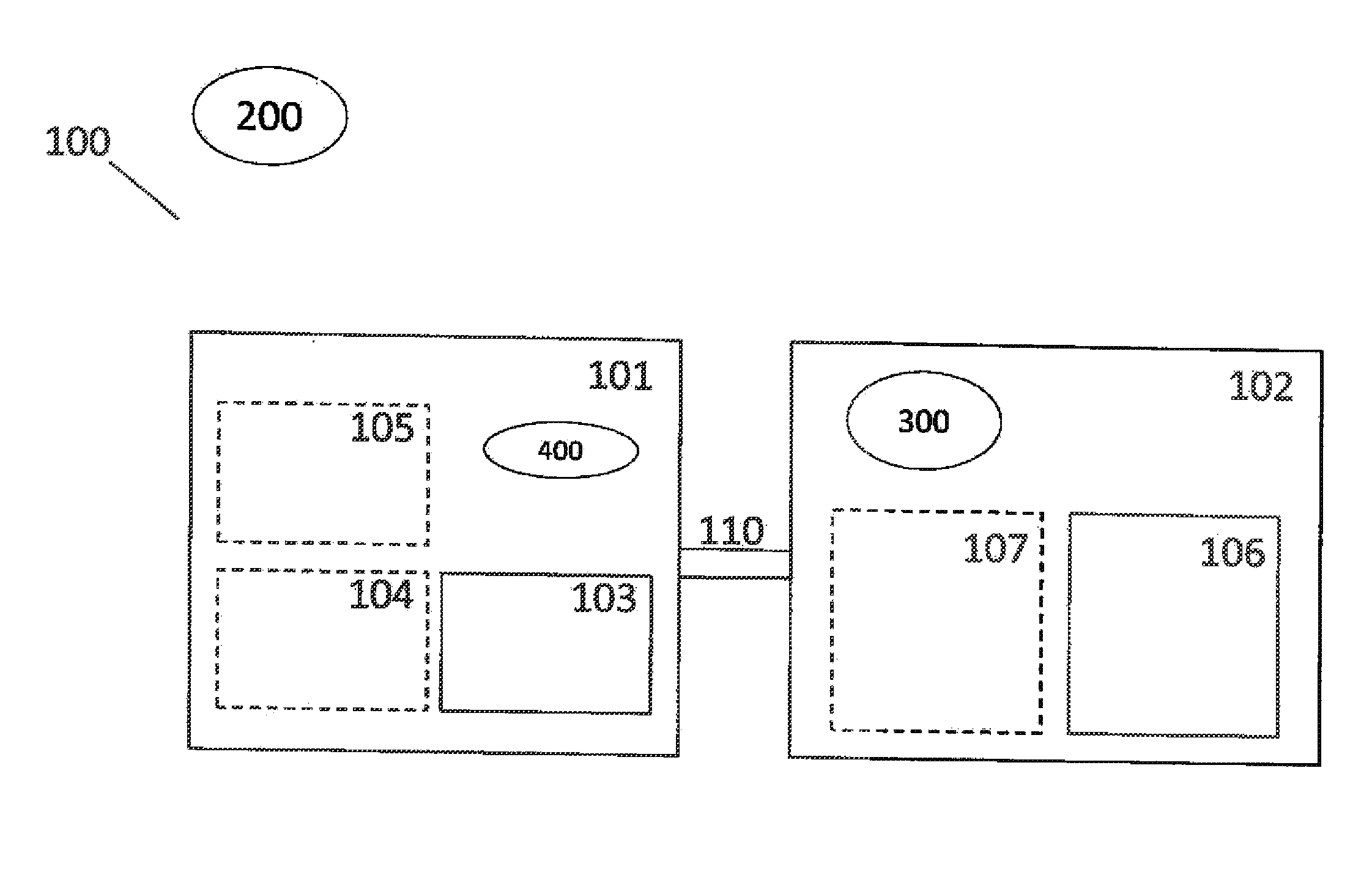
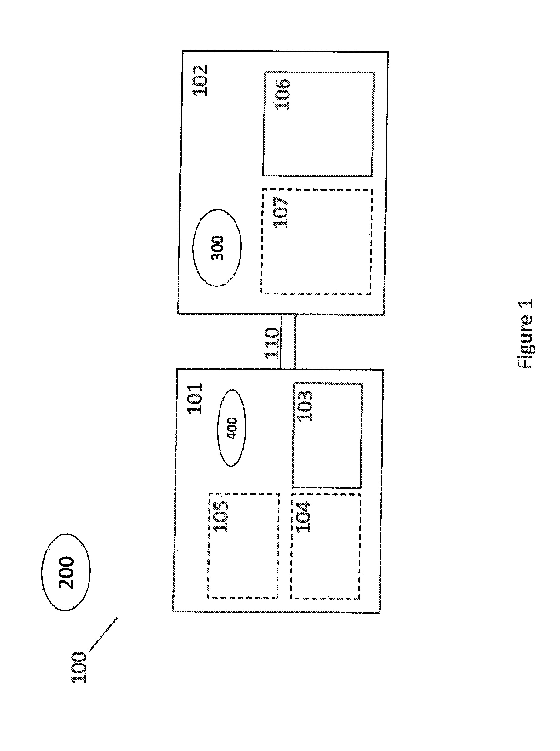
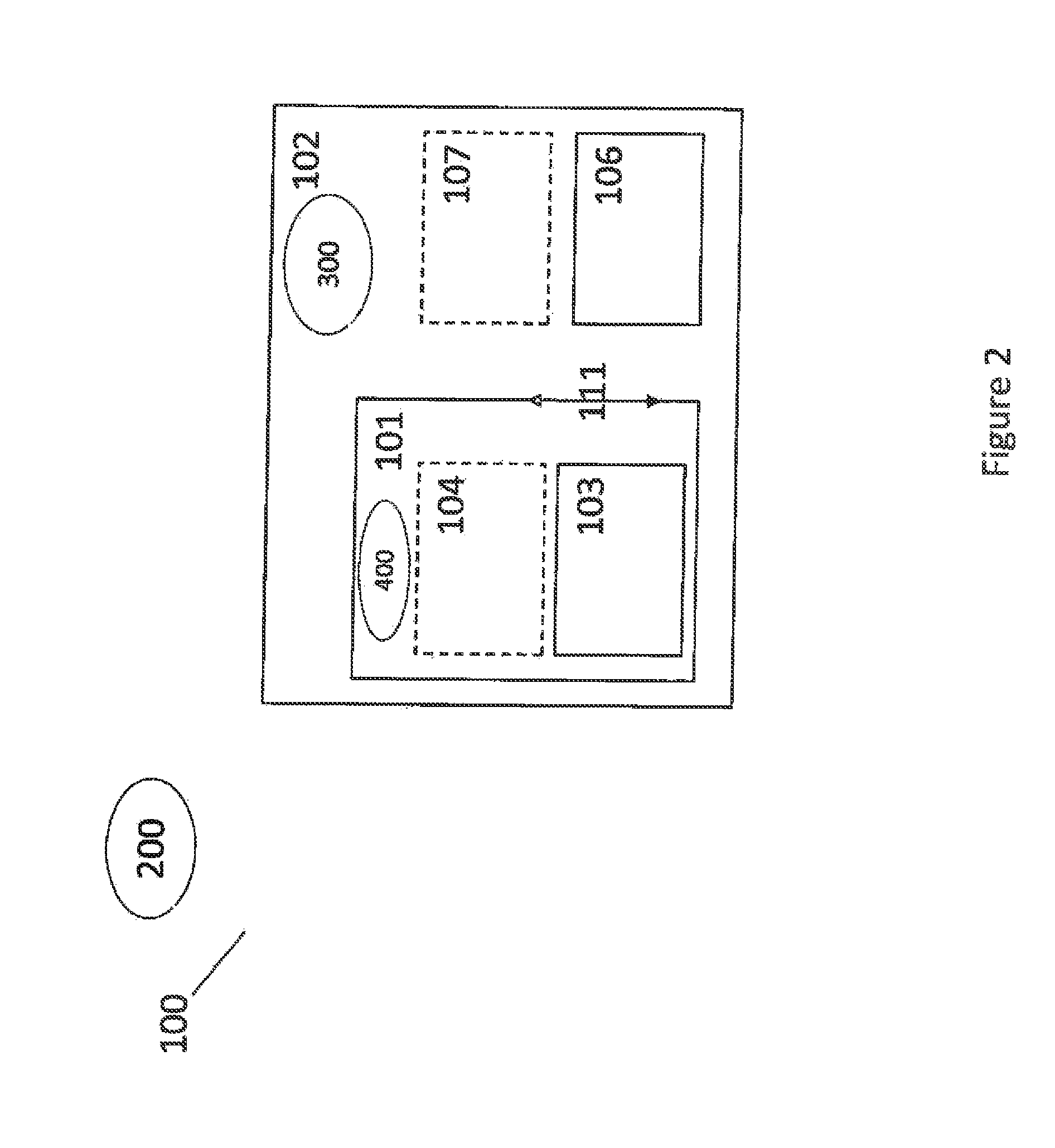
An apparatus (100) for performing atomic force microscopy is disclosed. The apparatus comprises an AFM measurement unit (102) configured to operate in a first controlled atmosphere (300) and a pretreatment unit (101) configured to operate in a second controlled atmosphere (400), the second controlled atmosphere being different from the first controlled atmosphere. The pretreatment unit is connected to the AFM measurement unit. In one embodiment, the second controlled atmosphere is a vacuum atmosphere, whereas the first controlled atmosphere includes at least an inert gas.

Description

CROSS-REFERENCE TO RELATED APPLICATIONS[0001]Priority is hereby claimed to U.S. 61 / 668,333, filed Jul. 5, 2012 and EP 12176325, filed Jul. 13, 2012, both assigned to the assignee of the present application and the subject matter of each of which is hereby incorporated by reference in its entirety.FIELD OF THE INVENTION[0002]The disclosed technology is related to an apparatus and a method for performing atomic force microscopy, more specifically for performing electrical characterization using atomic for microscopy.BACKGROUND[0003]Atomic force microscopy (AFM) is a type of scanning probe microscopy (SPM) that provides high resolution, three-dimensional (3D) imaging by scanning a sharp tip, typically positioned at the end of a cantilever, across the surface of a sample. The whole of the tip and cantilever is commonly referred to as a probe. By using a laser light which is focused on the back of the cantilever during scanning and by detecting the reflected light by a photodiode, it is ...

Claims


Application Information

Patent Timeline
Patent Type & Authority Applications(United States)
IPC IPC(8): G01Q30/16G01Q30/12
CPCG01Q30/12G01Q30/16B82Y35/00
Inventor PAREDIS, KRISTOFVANDERVORST, WILFRIED
Owner BRUKER NANO INC
Learn More