
Wind farm

a wind farm and wind power technology, applied in the field of wind farms, can solve problems such as affecting the overall efficiency of the wind farm, and achieve the effects of reducing relative power loss, shortening distances, and being more efficien

Inactive Publication Date: 2015-08-13
WOBBEN PROPERTIES GMBH
View PDF15 Cites 8 Cited by
  • Summary
  • Abstract
  • Description
  • Claims
  • Application Information

AI Technical Summary

Benefits of technology

The present invention proposes a DC voltage wind farm grid and wind turbines that only feed DC current and voltage into this grid. This reduces the loss of performance inside the wind farm and increases its efficiency. The feed-in device detects the grid status and allows for the appropriate values, ensuring that any requirements of the grid are met. The wind turbines no longer require frequency inverters, which leads to more efficient operation. The high voltage in the DC voltage grid reduces transmission losses and the use of a medium-voltage transformer may be redundant. The synchronous generator in the wind turbine produces reliable alternating current, which can be directly operated without interconnected gears. The wind turbines are variable speed turbines that can adapt to the wind speed.

Problems solved by technology

However, the disadvantage in this case is that losses can occur at every wind turbine and in an internal wind farm grid, which creates a coupling between the wind turbines and the collective grid injection point, which could impair the overall efficiency of the wind farm as a result.

Method used


Image

  • Wind farm
  • Wind farm
  • Wind farm

Examples


Embodiment Construction

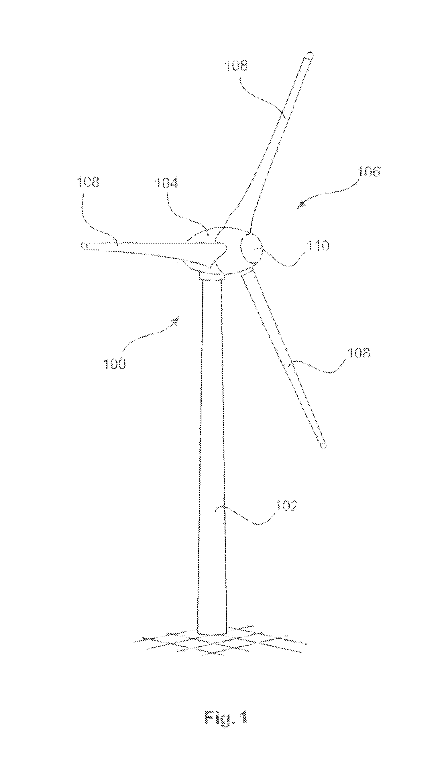
[0029]FIG. 1 shows a wind turbine 100 with a tower 102 and nacelle 104. An aerodynamic rotor 106 with three rotor blades 108 and a spinner 110 is located on the nacelle 104. The rotor 106 is set in operation by the wind in a rotating movement and thereby drives a generator in the nacelle 104.

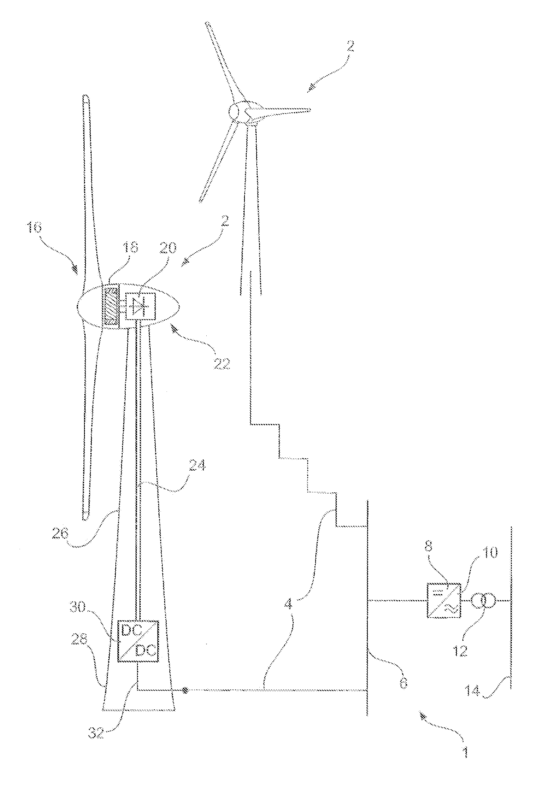
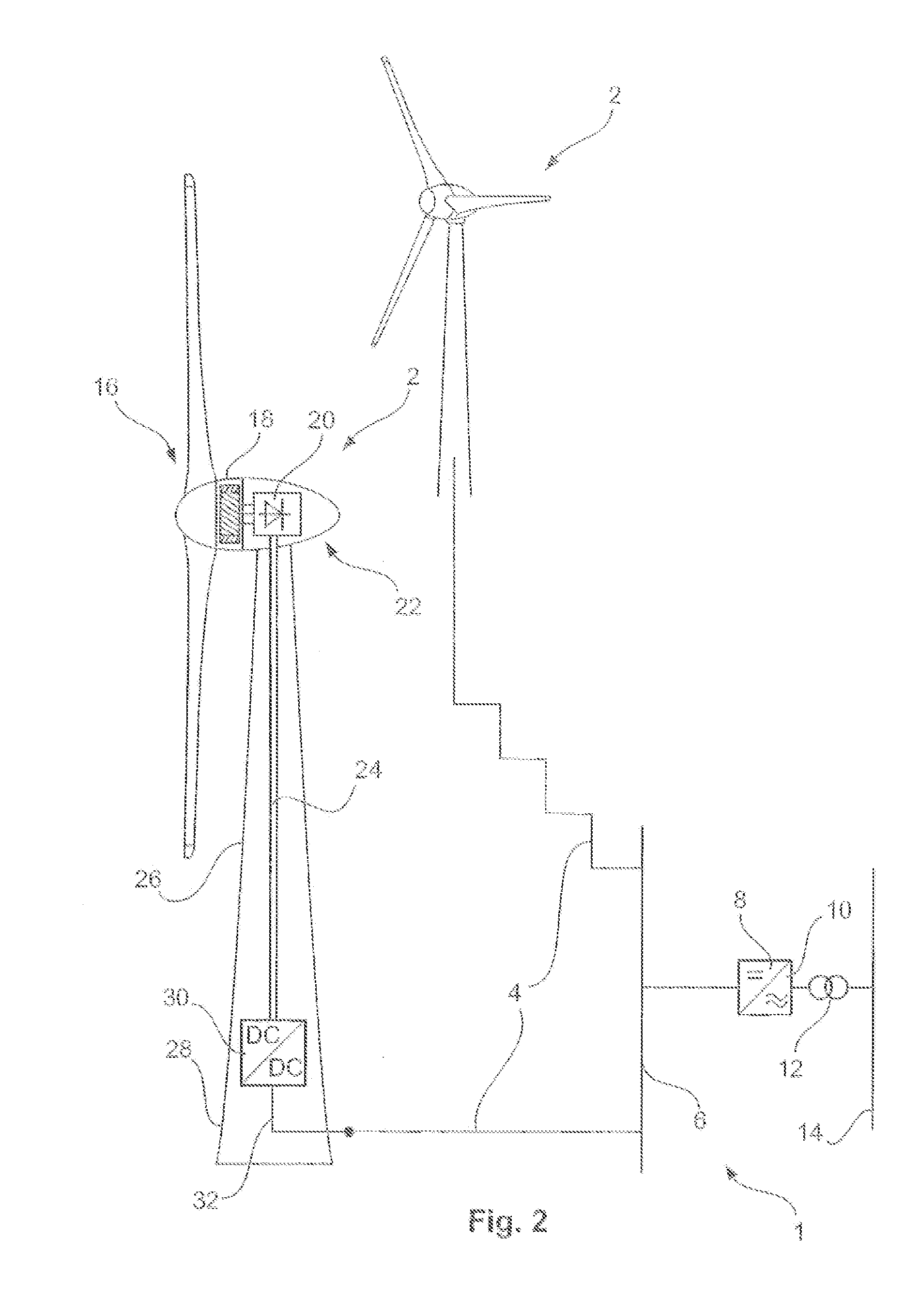
[0030]FIG. 2 shows a wind farm 1, which has two wind turbines 2 as an example, one of which is annotated in more detail. These details were not repeated for the other turbine for the sake of simplicity, but it is to be noted that some of its details of the other turbine may be different. Both wind turbines 2 are connected by a DC voltage line 4 and a DC voltage busbar 6 to a collective inverter 8 or multi-input inverter. The collective inverter 8 generates alternating current with an AC voltage from the DC voltage or the direct current from the busbar 6 at its output 10 and supplies this into an electrical supply grid 14, via a transformer 12, which here is designed to be a medium-voltage transf...


PUM


Abstract

The invention concerns a wind farm for generating electrical energy from wind, including at least 2 wind turbines for producing the electrical energy and a collective injection device for injecting the electrical energy generated, or part of it, into an electrical supply grid, whereby the wind turbines are connected to the injection device via an electrical DC voltage grid, in order to supply the electrical energy generated using the wind turbines as electrical direct current to the injection device.

Description

BACKGROUND[0001]1. Technical Field[0002]This invention relates to a wind farm for producing electrical energy from wind and for injecting the generated electrical energy into an electrical supply grid. This invention also relates to a method for injecting electrical energy generated on a wind farm by multiple wind turbines.[0003]2. Description of the Related Art[0004]It is generally known that electrical energy is generated by wind turbines from wind, where the term “generate” is used to describe that energy from the wind is converted into electrical energy. Often, multiple wind turbines are grouped together in one wind farm. Such a wind farm then has a collective injection point for supplying electrical energy into an electrical supply grid attached to it. All wind turbines in the wind farm therefore supply electrical energy into the electrical supply grid via this collective injection point.[0005]For example, supplying takes place in such a way that every wind turbine provides its...

Claims


Application Information

Patent Timeline
IPC IPC(8): F03D9/00H02J3/38
CPCH02J3/38F03D9/005H02J3/386F03D9/257H02J3/36Y02E10/72Y02E60/60H02J2300/28H02J3/381Y02E10/76H02J3/04
Inventor BEEKMANN, ALFRED
Owner WOBBEN PROPERTIES GMBH
Learn More