
Vehicle and contactless power supply system

a power supply system and contactless technology, applied in the direction of battery/fuel cell control arrangement, propulsion by capacitors, rail devices, etc., can solve the problems of power transmission unit input impedance fluctuation and power transmission efficiency decline, so as to prevent a decrease in power transmission efficiency

Active Publication Date: 2015-08-13
TOYOTA JIDOSHA KK +1
View PDF6 Cites 42 Cited by
  • Summary
  • Abstract
  • Description
  • Claims
  • Application Information

AI Technical Summary

Benefits of technology

The invention is a system that prevents a decrease in power transfer efficiency in a contactless power supply system that includes a vehicle and a power transmitting device. This means that the system is designed to maintain the efficiency of power transfer even during use. This can improve the overall performance of the contactless power supply system and make it more reliable and durable.

Problems solved by technology

For example, if an occupant gets on to the vehicle or gets off from the vehicle or a baggage is loaded into a trunk room or unloaded from the trunk room while power transmitting operation is being carried out from the power transmitting device to the power receiving device (vehicle), the vehicle height varies accordingly, so the input impedance of the power transmitting unit may fluctuate and the power transfer efficiency may decrease.

Method used


Image

  • Vehicle and contactless power supply system
  • Vehicle and contactless power supply system
  • Vehicle and contactless power supply system

Examples


Embodiment Construction

[0037]Hereinafter, an embodiment of the invention will be described in detail with reference to the accompanying drawings. Like reference numerals denote the same or corresponding components in the drawings, and the description thereof is not repeated.

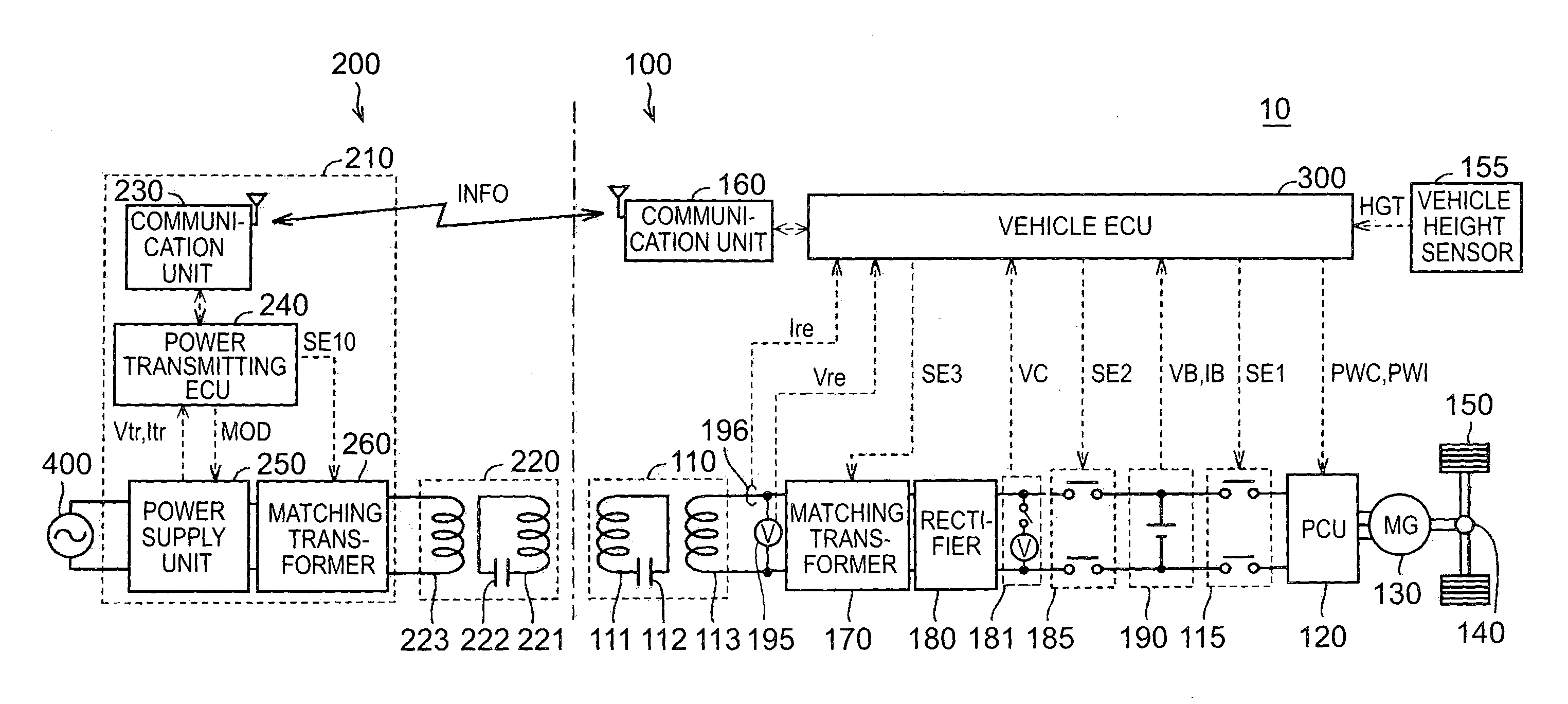
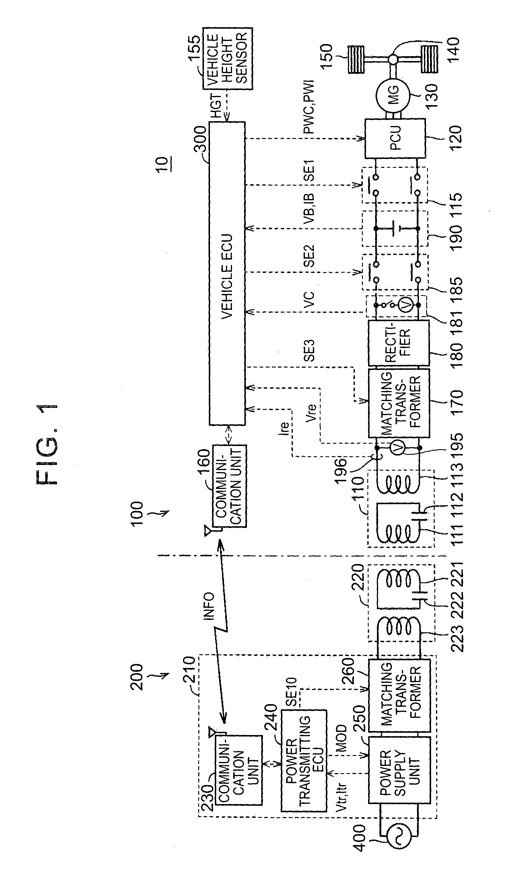
[0038]The configuration of a contactless power supply system according to the present embodiment will be described. FIG. 1 is an overall configuration view of a vehicle power supply system (i.e., contactless power supply system) 10 according to the present embodiment. The vehicle power supply system 10 includes a vehicle 100 and a power transmitting device 200. As shown in FIG. 1, the power transmitting device 200 includes a power supply device 210 and a power transmitting unit 220. The power supply device 210 generates alternating-current power having a predetermined frequency. For example, the power supply device 210 generates high-frequency alternating-current power upon reception of electric power from a commercial power supply 400...


PUM


Abstract

A contactless power supply system contactlessly supplies electric power from a power transmitting device to a vehicle. The vehicle includes a power receiving unit contactlessly receiving electric power from the power transmitting device, an electrical storage device storing electric power received by the power receiving unit, and a vehicle ECU. The power transmitting device includes a power supply unit, a power transmitting unit contactlessly supplying electric power, supplied from the power supply unit, to the power receiving unit and a matching transformer used to adjust an impedance between the power supply unit and the power transmitting unit. The vehicle ECU is able to output, to the power transmitting device, a command to adjust the matching transformer, and sets an impedance of the matching transformer on the basis of a power transfer efficiency between the power transmitting unit and the power receiving unit while the electrical storage device is being charged.

Description

BACKGROUND OF THE INVENTION[0001]1. Field of the Invention[0002]The invention relates to a vehicle and a contactless power supply system and, more particularly, to a technique for improving power transfer efficiency in a contactless power supply system.[0003]2. Description of Related Art[0004]In recent years, contactless wireless power transfer that does not use a power cord or a power transmission cable has become a focus of attention, and it has been suggested that the contactless wireless power transfer is applied to an electric vehicle, a hybrid vehicle, or the like, of which an in-vehicle electrical storage device is chargeable by a power supply outside the vehicle, (hereinafter, also referred to as “external power supply”).[0005]In such a contactless power supply system, in order to improve power transfer efficiency, it is important to match impedance between a power transmitting side and a power receiving side.[0006]Japanese Patent Application Publication No. 2012-034494 (JP ...

Claims


Application Information

Patent Timeline
IPC IPC(8): B60L11/18H02J7/00B60L50/16B60M7/00H01F38/14
CPCB60L11/182H02J5/005H02J7/025B60L53/12B60L55/00B60L50/16B60L58/12B60L53/36B60L50/40B60L50/51B60L15/2009B60L2210/40B60L2210/30B60L2220/14B60L2240/547B60L2240/549B60L2240/545B60L2240/70B60L2240/80B60L2240/12B60L2240/421B60L2240/423H02J7/00036Y02T90/16Y02T10/7072Y02T10/70Y02T90/14Y04S10/126B60L53/122B60L53/126H02J2310/48H02J50/90Y02E60/00Y02T10/64Y02T10/72Y02T90/12H02J50/12
Inventor ICHIKAWA, SHINJIMAKAMURA, TORUTOKUYAMA, KAZUMA
Owner TOYOTA JIDOSHA KK
Learn More