Biophotonic Measurement Apparatus and Biophotonic Measurement Method Using Same

a biophotonic measurement and biophotonic technology, applied in the field of biophotonic measurement apparatus, can solve the problems of difficult application, difficult application to two-dimensional imaging used in brain function measurement, and difficulty in stable signal acquisition, and achieve the effect of reducing temporal and personal costs and stabilizing a light reception signal

Inactive Publication Date: 2015-08-13
HITACHI LTD
View PDF4 Cites 7 Cited by
  • Summary
  • Abstract
  • Description
  • Claims
  • Application Information

AI Technical Summary

Benefits of technology

[0021]According to the present invention, stabilization of a light reception signal can be implemented by adjusting the attenuation amount of light to be transmitted or received, after consideration of a difference in transmittance among individual subjects and measurement regions. In addition, the attenuation amount of light on a waveguide path of each of the light transmitters and the light receivers can be adjusted automatically or manually by an operator of the apparatus with ease and efficient signal acquisition that has been reduced in temporal and personal costs can be implemented.

Problems solved by technology

However, this method presupposes that the multi-SD measurement data can be used, and in a case where a proper signal cannot be acquired over each SD distance, for example, when the detector is saturated because an amount of light is large, it becomes difficult to apply it.
Although this method is suited for measurement in a one-dimensional direction, it is difficult to apply it to two-dimensional imaging used in brain function measurement and so forth.
Also in this method, that the multi-SD measurement data can be used is set as a presupposition and stable signal acquisition becomes a problem.
Although there also exist a method of adjusting light reception sensitivity in time division and a method of changing the power of a light source in time division when a certain light transmitter or light receiver is to be commonly used for measurement of the plurality of different SD distances by the multi-SD system as described in Non-Patent Literature 3, since probes are to be highly densely arranged in the multi-SD, there is such a problem that measurement in time division results in deterioration of time resolution.
Further, in a case where measurement of, for example, the SD distances 5 mm and 30 mm is simultaneously performed still in a case where measurement is performed in time division, there is a difference in detected light amount of at least four digits as shown in FIG. 3, a highly accurate and multi-stage amplification circuit and so forth become necessary in control by an electromagnetic action, and an increase in production cost is induced.
In a case where the optical filter is not used, there was the possibility that appropriate gain setting for the detector cannot be performed against a difference in detected amount of light from a plurality of light sources exceeding the dynamic range of the detector.
In a case where the optical filter is used, it is necessary to once remove the optical fiber on the probe side or the apparatus main body side and there was such a problem that it takes time and labor.

Method used


Image

  • Biophotonic Measurement Apparatus and Biophotonic Measurement Method Using Same
  • Biophotonic Measurement Apparatus and Biophotonic Measurement Method Using Same
  • Biophotonic Measurement Apparatus and Biophotonic Measurement Method Using Same

Examples


first embodiment

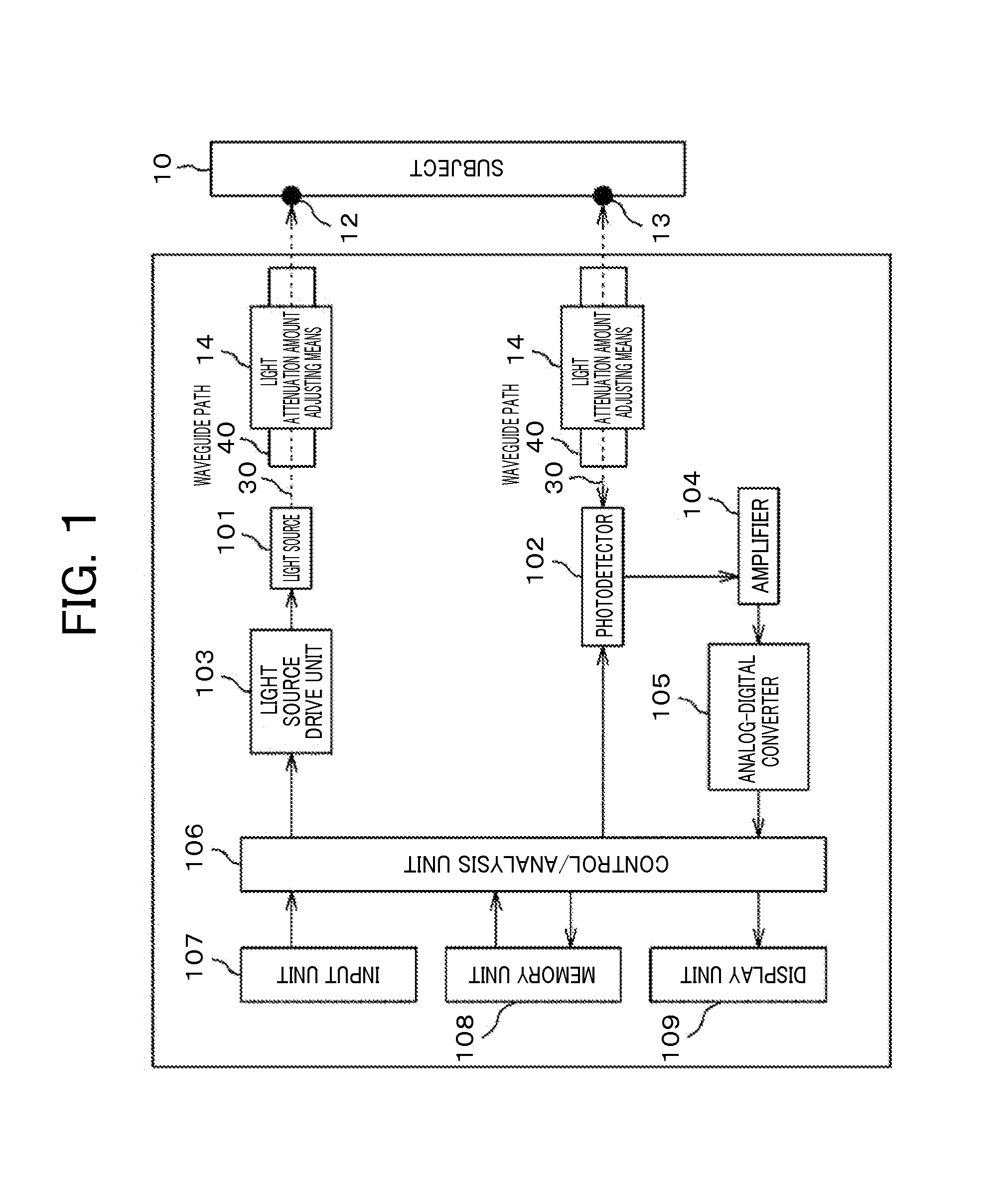
[0052]In FIG. 1, one example of an apparatus configuration of a biophotonic measurement apparatus of the present invention is shown. In the biophotonic measurement apparatus that makes light incident upon a living body and detects the light that has been scattered / absorbed and propagated in the living body and has gone out of it, light 30 irradiated from one or a plurality of light source(s) 101 included in an apparatus main body 20 is made incident upon a subject 10 via a waveguide path 40. The light 30 is incident into the subject 10 from an irradiation point 12, is transmitted and propagated in the subject 10, and is thereafter detected by one or a plurality of photodetector(s) from a detection point 13 located at a position apart from the irradiation point 12 via the waveguide path 40. The SD distance is defined by the distance between the irradiation point 12 and the detection point 13 as aforementioned.

[0053]Here, one or the plurality of light source(s) 101 is / are a semiconduc...

second embodiment

[0073]Next, a calculation method for the brain contribution ratio using the multi-SD measurement data to be performed by the control / analysis unit 106 will be described. In Patent Literature 3, description is made on the separation method for the brain and skin derived signals, utilizing the signal amplitude or the SD distance dependency of the weight of the component obtained by the signal separation method. In FIG. 13, relations (a) between the SD distance and partial average optical path lengths of the scalp and the gray matter, (b) between the SD distance and the partial average optical path lengths of the cranial bone, the cerebrospinal fluid layer (CSF) and a gross optical path length that have been obtained by Monte Carlo simulation are respectively shown. The horizontal axis is the SD distance (mm) and the vertical axis is the optical path length (mm). In NIRS measurement, since the SD distance influences the penetration depth of the irradiated light, the depth of a target b...


PUM


Abstract

In a biophotonic measurement apparatus using a probe having a plurality of irradiation-detector distances (SD distances) in order to separate light absorption changes in a surface layer and a deep layer of a biological tissue on the basis of near infrared spectroscopy, light reception sensitivity is stabilized on each subject/each region by adjusting an attenuation amount of light to be transmitted or received. It has a light source, a detector for detecting light that has been irradiated from the light source to an irradiation point on the subject and propagated in the subject, a light attenuation amount adjusting means to be disposed on an optical path between the light source—the subject or a photodetector—the subject, an analysis unit for analyzing a signal and a display unit for display a result of analysis, the light source and the detector are respectively arranged such the SD distance defined as a distance between an irradiation point and a detection point is given in two or more kinds, the analysis unit analyzes a measurement signal and calculates a light attenuation adjustment amount for setting respective received light amounts within a predetermined range, and the light attenuation amount adjusting means makes attenuation amounts of light respectively adjustable from the result of analysis by changing an amount of light that is incident upon the detector.

Description

TECHNICAL FIELD[0001]The present invention relates to a biophotonic measurement apparatus using visible light or near infrared light.BACKGROUND ART[0002]There is a report that in a light detection signal and a biological signal (hereinafter, an NIRS signal) obtained by imaging a non-invasive optical brain function using Near-infrared spectroscopy (NIRS) including an optical topography method, since light is irradiated from above the scalp, there is the possibility that it may be influenced by a fluctuation in skin blood flow of the scalp. In consideration of the influence of the skin blood flow like this, methods of extracting / removing components thereof are being studied. Many of them are of the type that signal components from regions that are different in depth are acquired by a system of a plurality of irradiation-detector (light transmitter-light receiver) distances (hereinafter, SD (Source-Detector) distances), and a skin blood flow signal that is thought to influence measurem...

Claims


Application Information

Patent Timeline
Patent Type & Authority Applications(United States)
IPC IPC(8): A61B5/00
CPCA61B5/0042A61B5/0075A61B5/743A61B2560/02A61B5/4064A61B2562/0238A61B2576/026A61B5/7203A61B5/1455A61B5/14556
Inventor FUNANE, TSUKASAKIGUCHI, MASASHIFUJIWARA, MICHIYUKIKAGA, MIKIHIROTAKATERA, TSUYOSHI
Owner HITACHI LTD
Why Eureka
Try Eureka