
Reduction of turbocharger core unbalance with balance washer

Active Publication Date: 2015-08-06
BORG WARNER INC
View PDF3 Cites 47 Cited by
  • Summary
  • Abstract
  • Description
  • Claims
  • Application Information

AI Technical Summary

Benefits of technology

The present invention is based on the discovery that adding a thin washer between the nut and compressor wheel can improve balance. The washer should be thin and have high degree of planar parallelism. This prevents bending of the shaft and gouging of the compressor wheel. The invention requires parallelism of the washer, which can be measured using a micrometer caliper. The greater the parallelism, the better the ability to enhance balance.

Problems solved by technology

The present inventor investigated improving balance by adding off-the-shelf standard washers, and discovered that such washers have poor parallelism and high mass, and tended to do more harm than good.

Method used


Image

  • Reduction of turbocharger core unbalance with balance washer
  • Reduction of turbocharger core unbalance with balance washer
  • Reduction of turbocharger core unbalance with balance washer

Examples


Embodiment Construction

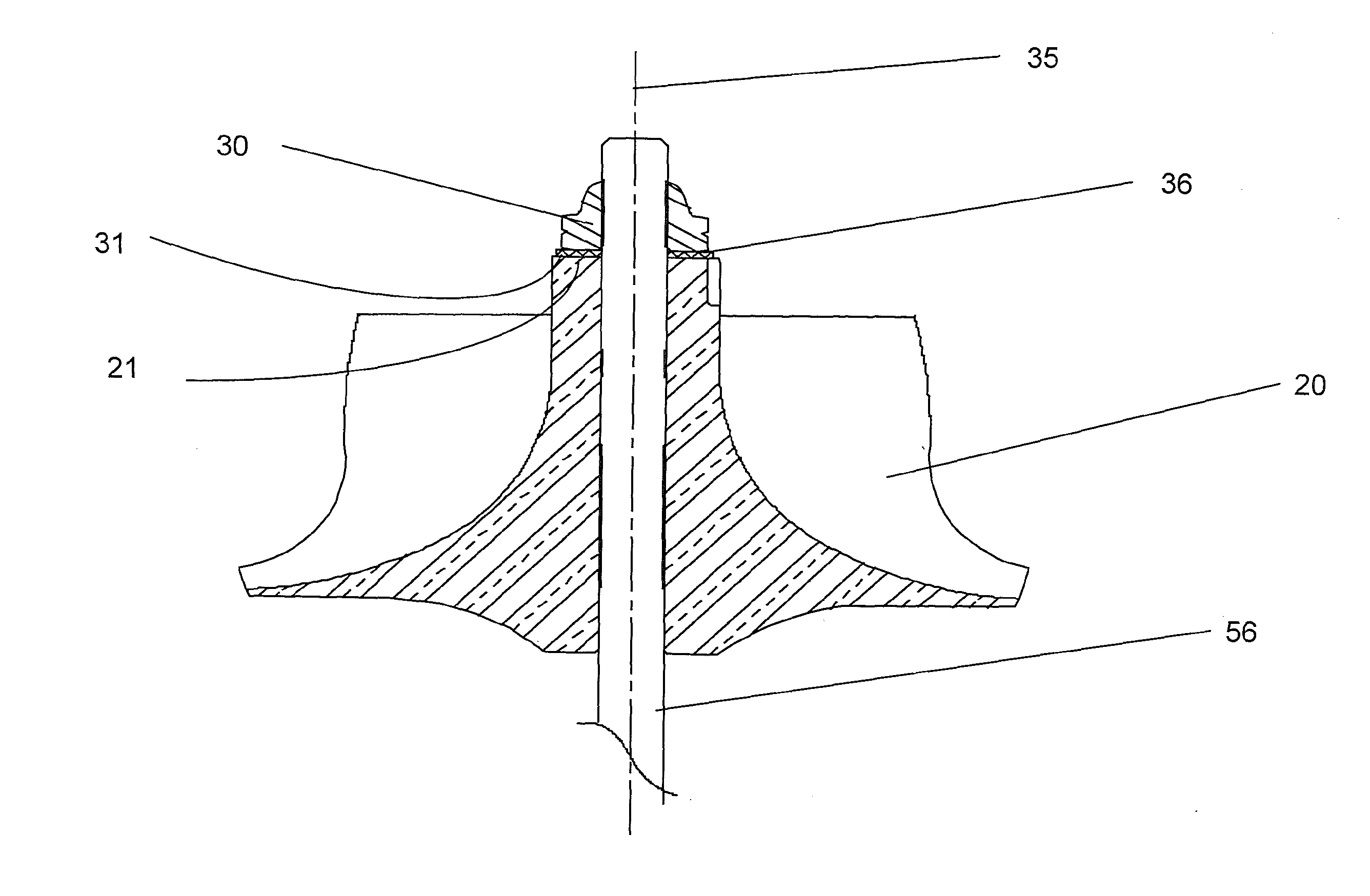
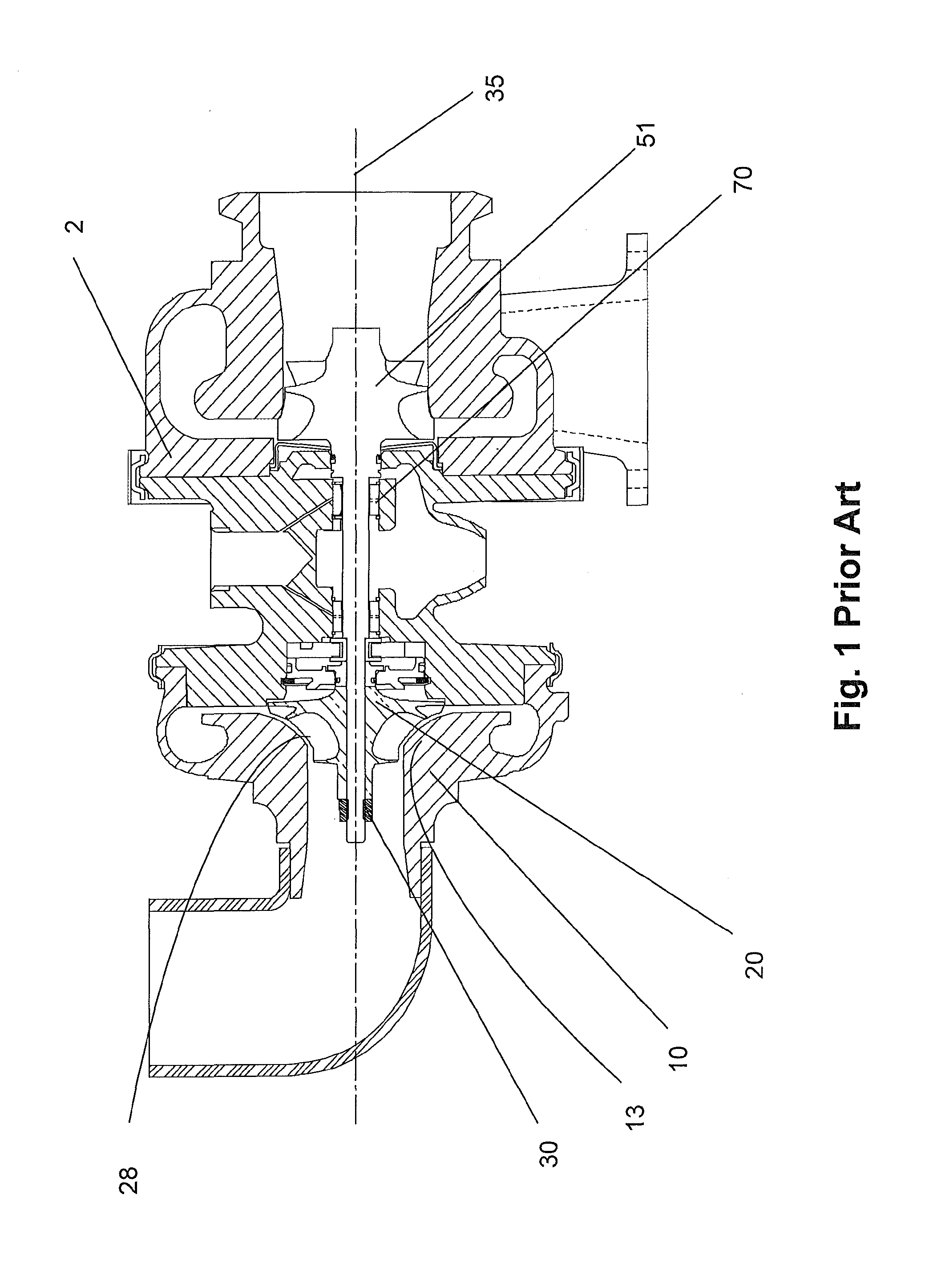
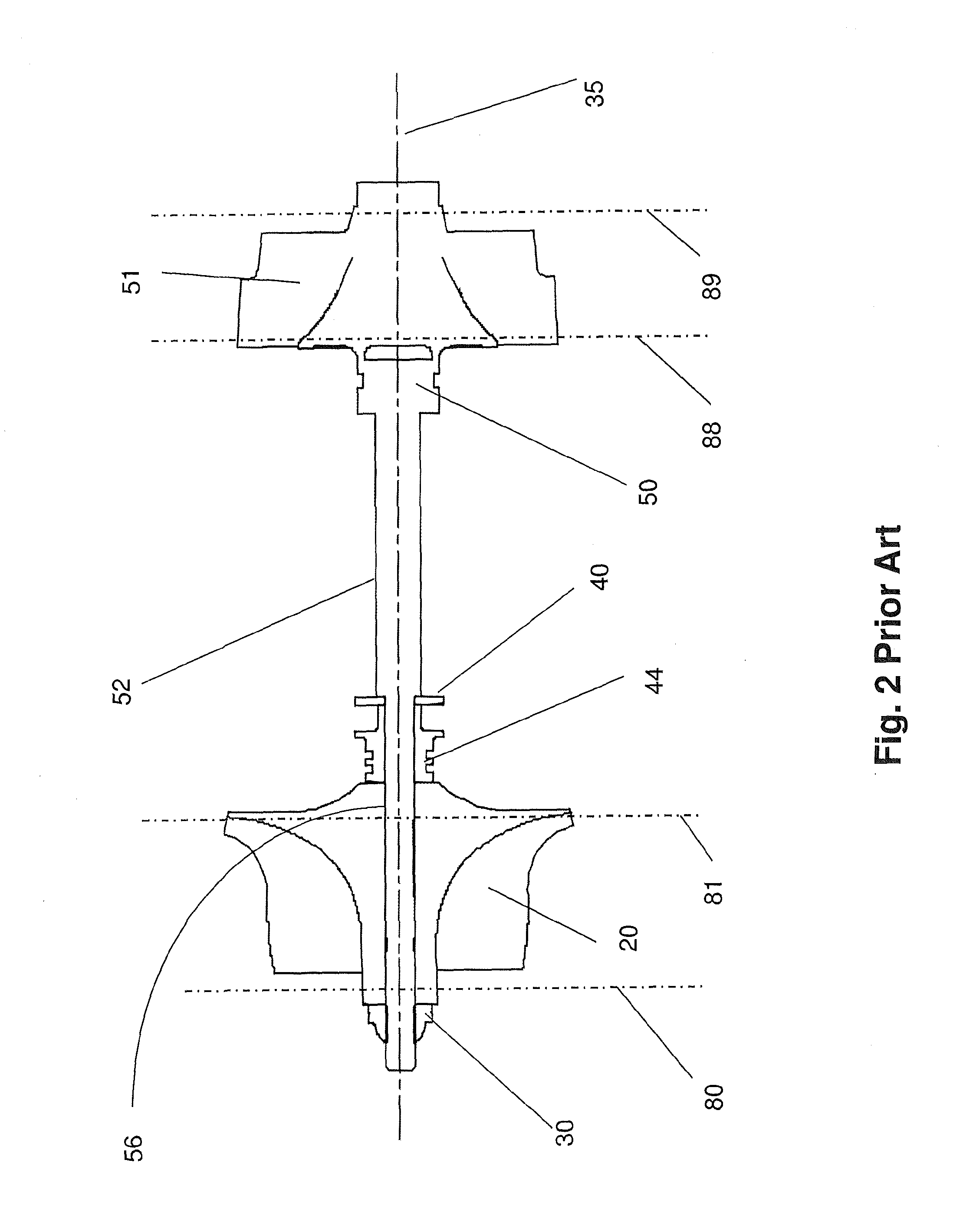
[0028]Turbochargers (FIGS. 1 and 2) extract energy from a vehicle exhaust flow, which enters the turbine housing (2) to drive a turbine wheel (51), which is located in the turbine housing. The turbine wheel is solidly affixed to the turbine end of a shaft, becoming the shaft and wheel assembly (50). A compressor wheel (20) is mounted the other end of the shaft, referred to as the “stub shaft” (56), and the wheel is held in position by the clamp load from a compressor nut (30). The primary function of the turbine wheel is providing rotational power to drive the compressor.

[0029]The compressor stage is mainly comprised of a wheel (20) and it's housing (10). Filtered air is drawn axially into the inlet of the compressor cover by the rotation of the compressor wheel (20). The power generated by the turbine stage to the shaft and wheel drives the compressor wheel to produce a combination of static pressure with some residual kinetic energy and heat.

[0030]In one aspect of compressor stage...


PUM

PropertyMeasurementUnit
Fractionaaaaaaaaaa
Hardnessaaaaaaaaaa
Surface roughnessaaaaaaaaaa

Abstract

Turbochargers operate at extremely high speed, so balance of the rotating core is of the utmost importance to turbocharger life. A special balancing washer is added to the clamping region between the compressor nut and the nose of the compressor wheel to aid in keeping the wheel, nut, and stub-shaft on the turbocharger axis and to thereby prevent introduction of core unbalance.

Description

FIELD OF THE INVENTION[0001]This invention eliminates a potential source of imbalance in high speed rotating assemblies, and in particular in rotating assemblies used in turbochargers.BACKGROUND OF THE INVENTION[0002]Turbochargers drive a compressor to deliver air at high density to the engine intake, allowing more fuel to be combusted, thus boosting the engine's horsepower. To do this, the rotating assembly of the turbocharger, comprising turbine wheel, compressor wheel, and shaft, may rotate at 80,000 RPM to 300,000 RPM. It is critical that the rotating assembly be balanced with a high degree of precision to improve efficiency and prevent premature wear.[0003]The turbine wheel is materially fused to the shaft to make a shaft-and-wheel assembly. The shaft-and-wheel assembly is finished as a very accurately machined, unitary component with shaft diameters ground to tolerances in the 2.5 micron regime; thus, its inherent balance is quite good.[0004]The compressor wheel, on the other ...

Claims


Application Information

Patent Timeline
IPC IPC(8): F04D29/66F16F15/34F04D17/10F16B43/00
CPCF16F15/322F16B43/00F01D5/027F16F15/34F04D17/10F04D29/668F05D2220/40F04D29/266F04D29/284F04D29/662Y10T29/49245F01D5/025
Inventor KING, DENNY
Owner BORG WARNER INC
Learn More