
Electric catalytic oxidizer

a catalytic oxidizer and electric technology, applied in the direction of catalytic material combustion, combustion types, separation processes, etc., can solve the problem of inpractical combustion of flames, and achieve the effect of minimizing energy use, structural mass, and containment volum

Active Publication Date: 2011-10-18
THE MARITAL TRUST ESTABLISHED UNDER ARTICLE FOURTH OF THE JAMES M CLEARY JR TRUST +1
View PDF19 Cites 4 Cited by
  • Summary
  • Abstract
  • Description
  • Claims
  • Application Information

AI Technical Summary

Benefits of technology

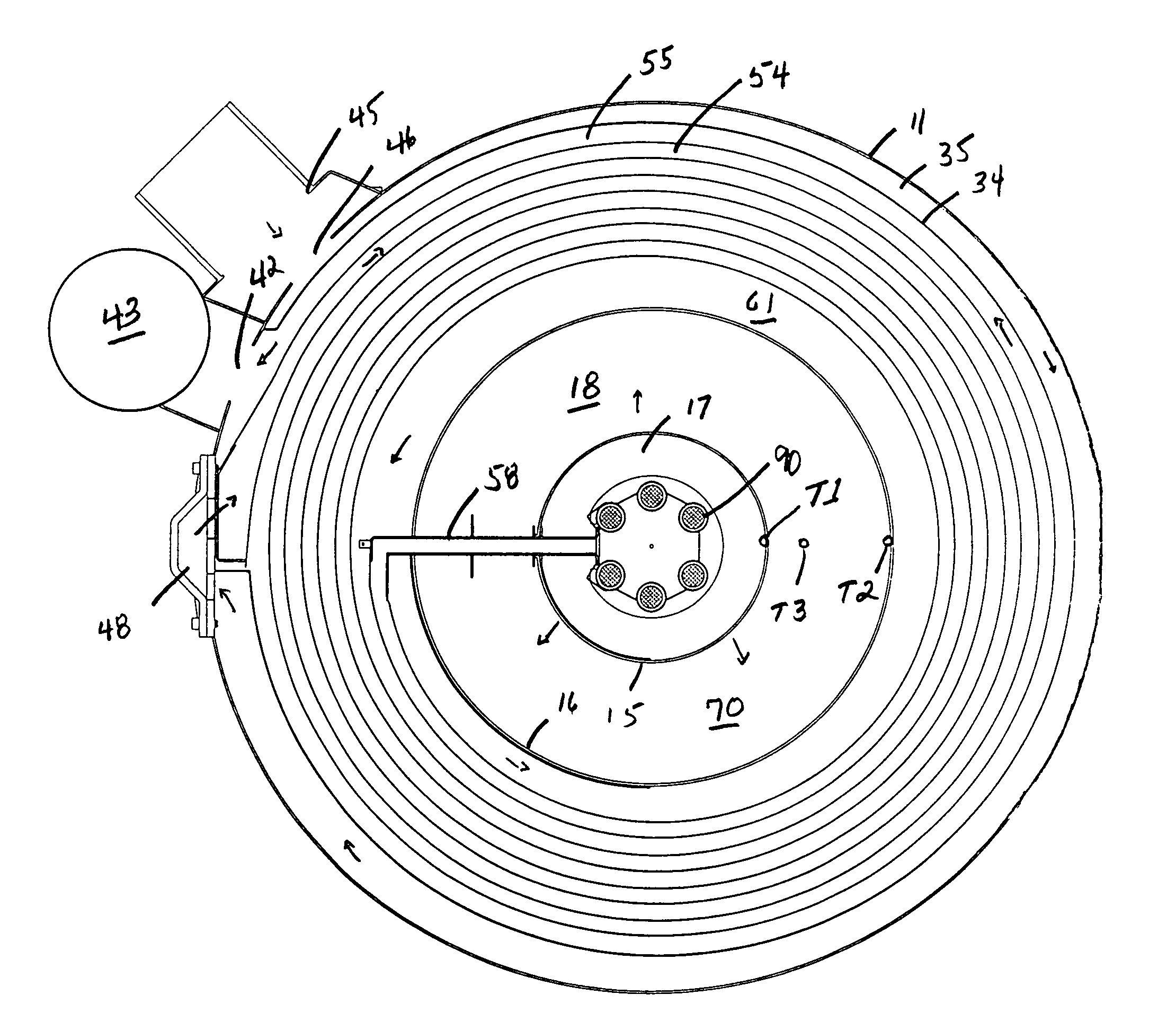
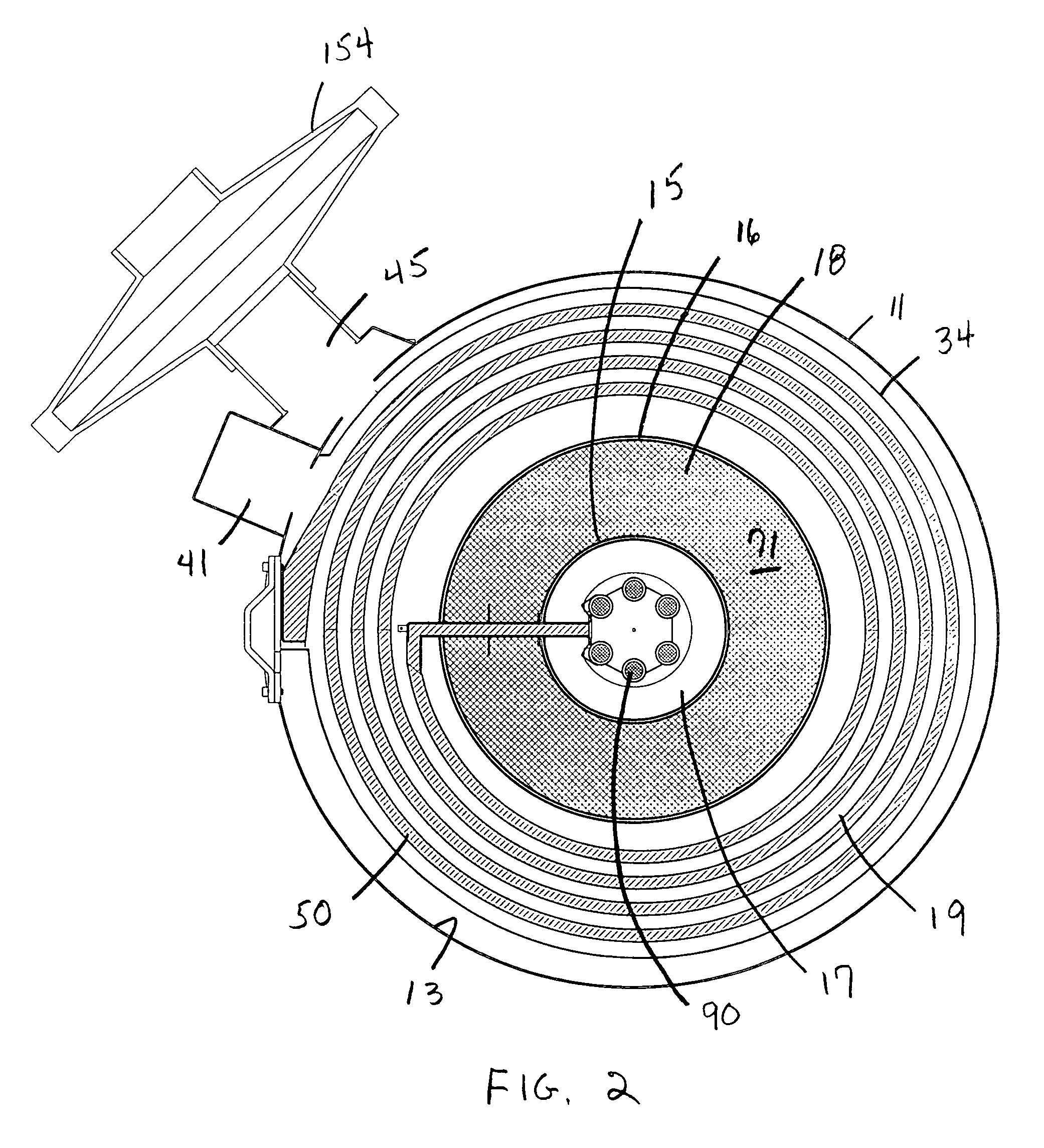
[0003]The primary objective of the present invention is to provide maximum heat recovery and reactor volume for a given amount of pressure containment volume and construction material. The present invention accomplishes this by providing a containment vessel having a spiral plate heat exchanger, a central catalyst chamber, a central heater, and essential flow pathways, forming a novel catalytic reactor providing efficient heat exchange for preheating reactants, while minimizing energy use, structural mass, and containment volume.
[0005]The present invention eliminates the need to combine the inlet spiral, heater assembly, inlet plenum, and catalyst chamber as a continuous sealed envelope. This requirement is avoided by an annular construction with radial flow with central heater, cylindrical inlet screen, cylindrical catalyst chamber and cylindrical outlet screen. A packed bed of catalyst closely contacts the upper and lower walls of the vessel and radial passage. In this way the packed bed of catalyst provides the necessary sealing to prevent untreated vapor mixture from reaching the exhaust side of the system.
[0006]The basic construction of the present invention enables the breakdown and disassembly of the reactor into simple elements while still maintaining a highly compact integrated system. The present invention eliminates the need for the core assembly, a separate containment for inlet and outlet plenum, and catalyst chamber as disclosed in applicant's prior '537 and '390 patents.

Problems solved by technology

Many applications involve very low concentrations of hydrocarbon where catalytic combustion is efficient, while flame combustion is not practical.

Method used


Image

  • Electric catalytic oxidizer
  • Electric catalytic oxidizer
  • Electric catalytic oxidizer

Examples


Embodiment Construction

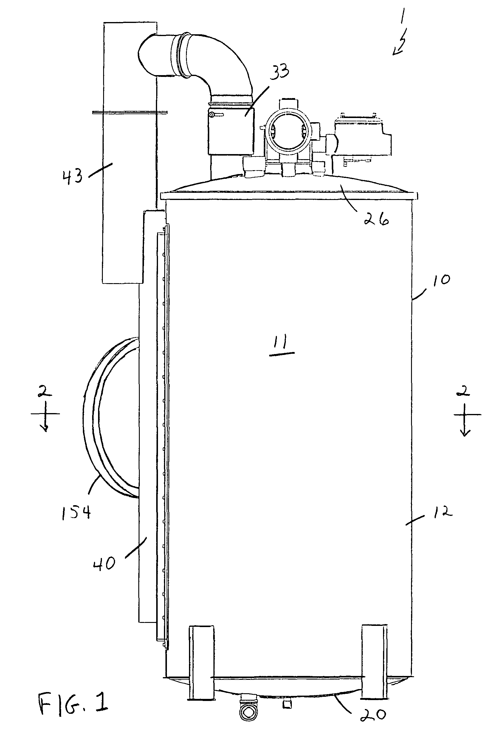
[0029]Referring to the drawings in detail wherein like elements are indicated by like numerals, there is shown an electric catalytic oxidizer 1 comprised of a containment vessel 10, a spiral heat exchanger 50 within said containment vessel, a heater assembly 90 centrally positioned within said containment vessel, a catalyst chamber 70 within said containment vessel and positioned between said spiral heat exchanger 50 and said heater assembly 90, and a plurality of essential flow pathways.

[0030]The containment vessel 10 has a bottom cover 20 from which a cylindrical side wall 11 extends vertically upward, said containment vessel 10 being generally cylindrical in shape, a vertical longitudinal axis of said cylindrical containment vessel being generally perpendicular to the bottom cover 20 of said containment vessel 10, said containment vessel 10 having a top cover 23 removably connected to said cylindrical side wall 11, said side wall, top cover and bottom cover defining a containment...


PUM

PropertyMeasurementUnit
Temperatureaaaaaaaaaa
Weightaaaaaaaaaa
Diameteraaaaaaaaaa

Abstract

A containment vessel having a spiral plate heat exchanger, a central catalyst chamber packed with particulate catalyst, a central heater, a plenum providing conductive flow access for a hydrocarbon-air mixture to and from the containment vessel interior, and essential flow pathways interconnecting the plenum section, heat exchanger, catalyst chamber and central heater. The spiral plate heat exchanger, catalyst chamber, and heater assembly occupy successively smaller annular regions within the containment vessel.

Description

BACKGROUND OF THE INVENTION[0001]This invention relates generally to catalytic oxidizers, and in particular, to an electric catalytic oxidizer for the treatment of hydrocarbon vapors from soil hydrocarbon-air vapor mixture extraction systems, and vapor from manufacturing processes.[0002]Typically the most common application of such catalytic oxidizers is in the destruction of vapors extracted in situ from soils that have been contaminated with hydrocarbons, typically by a hydrocarbon leak from a storage tank. Such applications normally involve the clean-up of vapors contained in an air stream generated during clean-up of hydrocarbon spills, i.e. soil vapor extraction systems. The advantage of a catalytic combustion process is that it can be operated at a much lower temperature and lower hydrocarbon concentration than is possible with ordinary flame combustion. Many applications involve very low concentrations of hydrocarbon where catalytic combustion is efficient, while flame combus...

Claims


Application Information

Patent Timeline
IPC IPC(8): B01D50/00B01J8/02F28D21/00
CPCB01J8/0257B01J8/0278B01J8/0285F23C13/00F28D9/04B01J2208/00061B01J2208/00203B01J2208/00221B01J2208/00407B01J2208/00415B01J2208/00495B01J2208/0053B01J2219/00198B01J2219/002B01J2219/00202B01J2219/00213B01J2219/00231
Inventor CLEARY, JAMES M.
Owner THE MARITAL TRUST ESTABLISHED UNDER ARTICLE FOURTH OF THE JAMES M CLEARY JR TRUST
Learn More