Glue gun

a glue gun and nozzle technology, applied in the field of glue guns, can solve the problems of clogging of the ball valve in the nozzle, the glue gun may become beyond repair, and the user may keep pulling the trigger, so as to achieve efficient bonding work, efficient heat and melt the adhesive, and the effect of large volum

Inactive Publication Date: 2015-07-30
TECHNOS CO LTD
View PDF0 Cites 15 Cited by
  • Summary
  • Abstract
  • Description
  • Claims
  • Application Information

AI Technical Summary

Benefits of technology

The invention is a glue gun that can quickly heat and melt hot melt adhesive, and then continuously inject it. This allows for efficient bonding in a short time. The glue gun has the advantage of increasing the contact area between the adhesive and the material it is bonding, resulting in faster heating and melting. Additionally, the glue gun can cut the adhesive into multiple pieces, allowing for easier heating and bonding. Additionally, the glue gun can hold a large amount of hot adhesive, ensuring continuous injection and efficient bonding.

Problems solved by technology

If a user does not understand this property sufficiently, the user may keep pulling a trigger while the hot melt adhesive have a high viscosity.
If the hot melt adhesive having a high viscosity is squeezed out, this would cause the clogging of a ball valve in a nozzle.
If this happens, the trigger cannot move, and the glue gun may become beyond repair.
In addition, the inside capacity of the conventional glue gun is small so that the conventional glue gun cannot inject the adhesive continuously.
This is troublesome in industrial use.

Method used


Image

  • Glue gun
  • Glue gun
  • Glue gun

Examples


Embodiment Construction

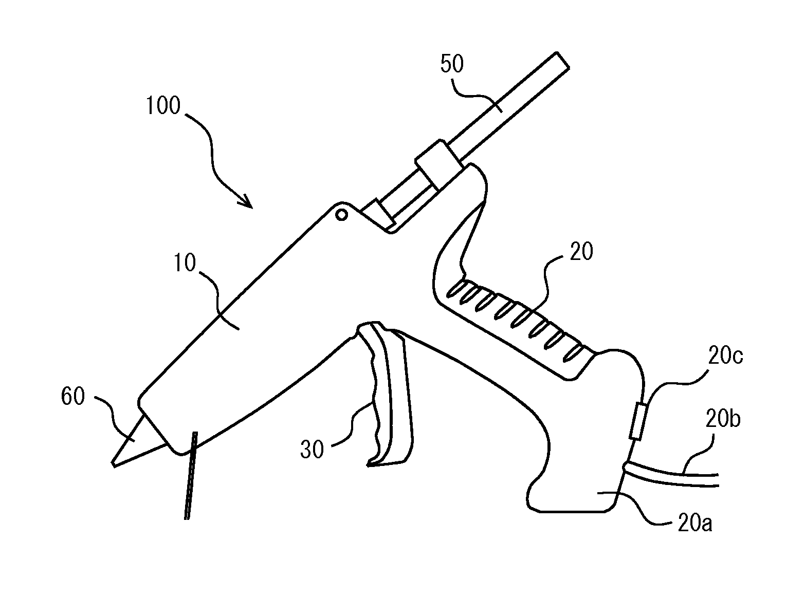
[0033]Now, an embodiment of the present invention will be described with reference to the accompanying drawings. FIG. 1 shows an outside appearance of a glue gun 100 according to an embodiment of the present invention. As illustrated, the glue gun 100 has a generally cylindrical main body 10, a handle 20 extending from the glue gun main body 10, and a trigger 30 at a connection between the handle 20 and the glue gun main body 10. The overall shape (outside appearance) of the glue gun is similar to a handgun or pistol.

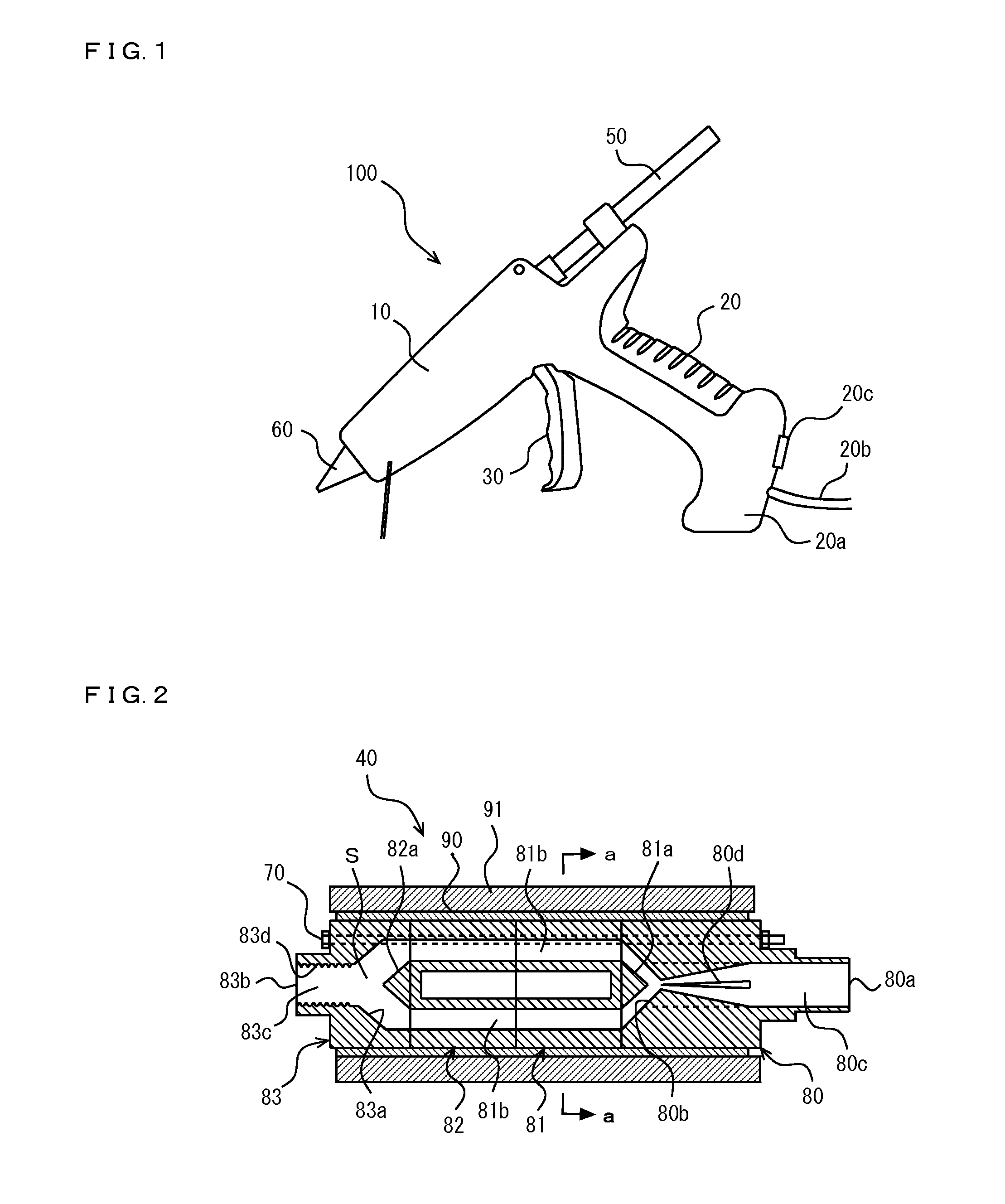
[0034]In the glue gun main body 10, there is a built-in melt portion 40 as shown in FIGS. 2 and 3. When the trigger 30 is repeatedly pulled, a stick-shaped hot melt adhesive (glue stick) 50 is introduced continuously into the melt portion 40. The melt portion 40 heats and melts the glue stick 50, and injects the melted glue from a nozzle 60 at a front end of the melt portion 40.

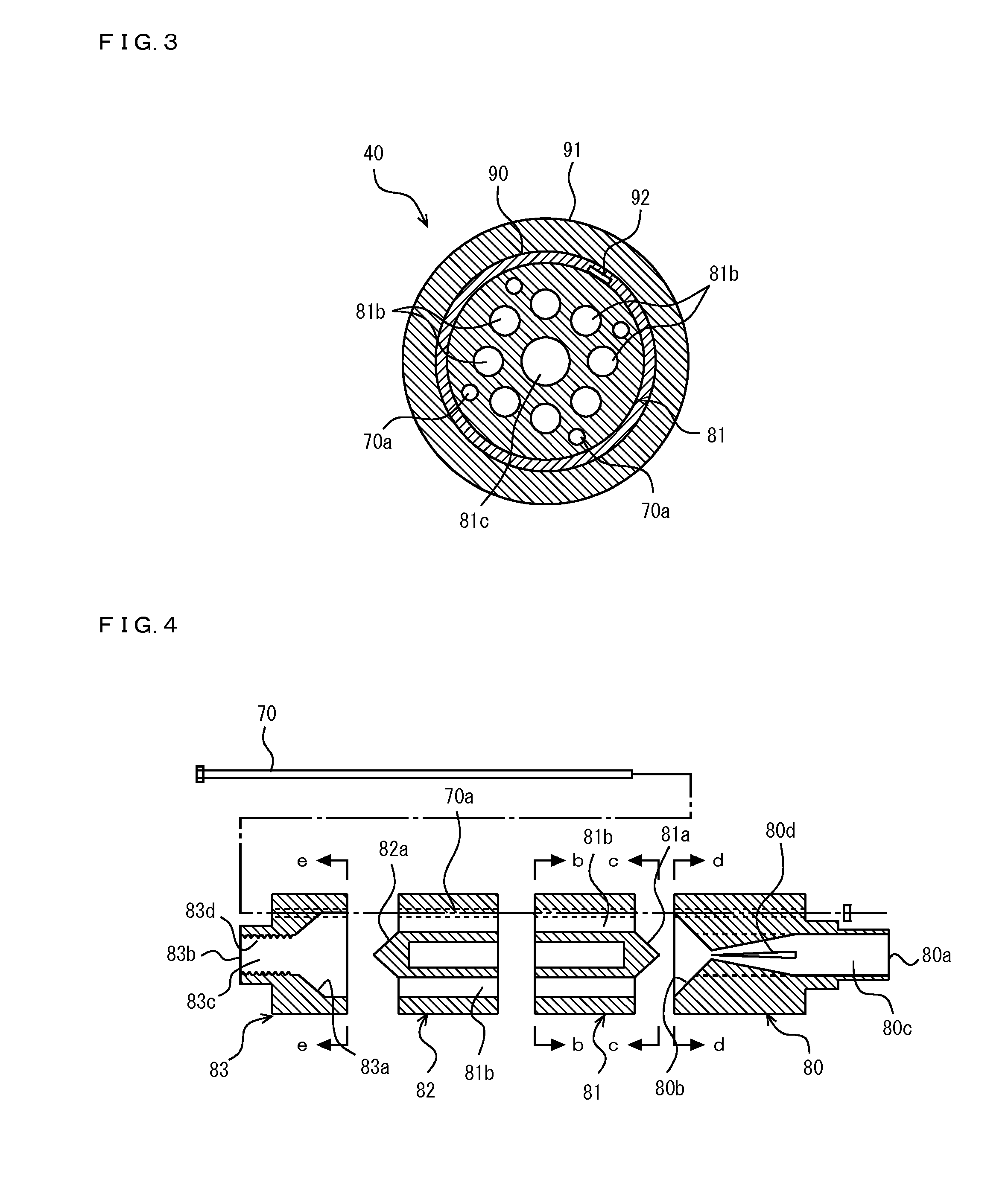
[0035]As shown in FIGS. 2 and 3, the melt portion 40 is made from a metal having a good therm...


PUM

PropertyMeasurementUnit
conical shapeaaaaaaaaaa
volumeaaaaaaaaaa
heightaaaaaaaaaa

Abstract

A glue gun includes a melt portion configured to receive a stick-shaped hot melt adhesive, and then heat, melt, and inject the hot melt adhesive. The melt portion has an inlet opening to receive the stick-shaped hot melt adhesive, and an outlet opening to inject liquid hot melt adhesive. The liquid hot melt adhesive is prepared by heating and melting the stick-shaped hot melt adhesive. The inlet opening communicates with the outlet opening via a plurality of passages.

Description

CROSS-REFERENCE TO RELATED APPLICATION[0001]The present application is a Continuation and claims benefit, pursuant to 35 U.S.C. §120, of International Patent Application No. PCT / JP2014 / 074192 filed on Sep. 12, 2014, which is based upon and claims benefit of priority from the prior Japanese Patent Application No. 2013-191465, filed on Sep. 17, 2013, which is incorporated by reference in its entirety herein.TECHNICAL FIELD[0002]The present invention relates to a glue gun that heats and melts a stick-shaped hot melt adhesive, and injects the hot melt adhesive.BACKGROUND ART[0003]Conventionally, a hot melt adhesive (hot glue) is used as an adhesive for closing (sealing) a corrugated paperboard carton, for packaging a medicine or cosmetics, for assembling a woodwork, and for other purposes. The hot melt adhesive is an adhesive that may include ethylene-vinyl acetate (EVA), or thermoplastic resin such as polyamide and acrylic resin. In professional use, an application device, which is ref...

Claims


Application Information

Patent Timeline
Patent Type & Authority Applications(United States)
IPC IPC(8): B05C17/005
CPCB05C17/0052B05C17/0053B05C5/001B05C11/1042B05C17/00546H05B3/42H05B2203/012
Inventor ONO, KAZUHIKO
Owner TECHNOS CO LTD
Why Eureka
Try Eureka