Metal and graphite laminate

a graphite and metal technology, applied in the field of laminate materials, can solve the problems of reducing the thickness of the metal layer,

Inactive Publication Date: 2015-07-23
R A INVESTMENT MANAGEMENT S A R L
View PDF4 Cites 5 Cited by
  • Summary
  • Abstract
  • Description
  • Claims
  • Application Information

AI Technical Summary

Benefits of technology

The invention is about a special sheet material that has a hard layer with raised structures on its surface. These structures are made by piercing the surface of a graphite foil material that is mated to the hard layer. The resulting material has a unique texture and can be used as a noise damping shim in brairng systems. The technical effect of this invention is the creation of a special sheet material that has a unique texture and can be used as a noise damping shim in brabraking systems.

Problems solved by technology

As a result, the sheeting is weakened by the perforations.
Also, if the metal sheet is only laminated on one side, the unlaminated metal surface is not smooth because of the perforations.
Furthermore, the thickness of the metal layer is limited because it must be thin enough to allow the puncher needles to penetrate it.
High frictional forces are generated during this sliding movement which can cause squeal.
Like a stick of chalk forced at an angle across a rigid board, friction can lead to very severe vibrational noise.
As well, these recurring forces can lead to fretting and chipping of the piston rim.
Brake squeal is a very expensive problem for car and brake manufacturers as customers invariably want the noise remedied under warranty even if the brakes are otherwise perfect.
None have been entirely satisfactory.
While graphite sheeting has various properties that make it very suitable for noise reduction, it is unsuitable by itself for use as a shim because of its brittleness.
Laminates using graphite foil and tanged metal are generally not suitable because such tanged metal is not strong enough to be well suited for use in brake pad shims.

Method used


Image

  • Metal and graphite laminate
  • Metal and graphite laminate
  • Metal and graphite laminate

Examples


Embodiment Construction

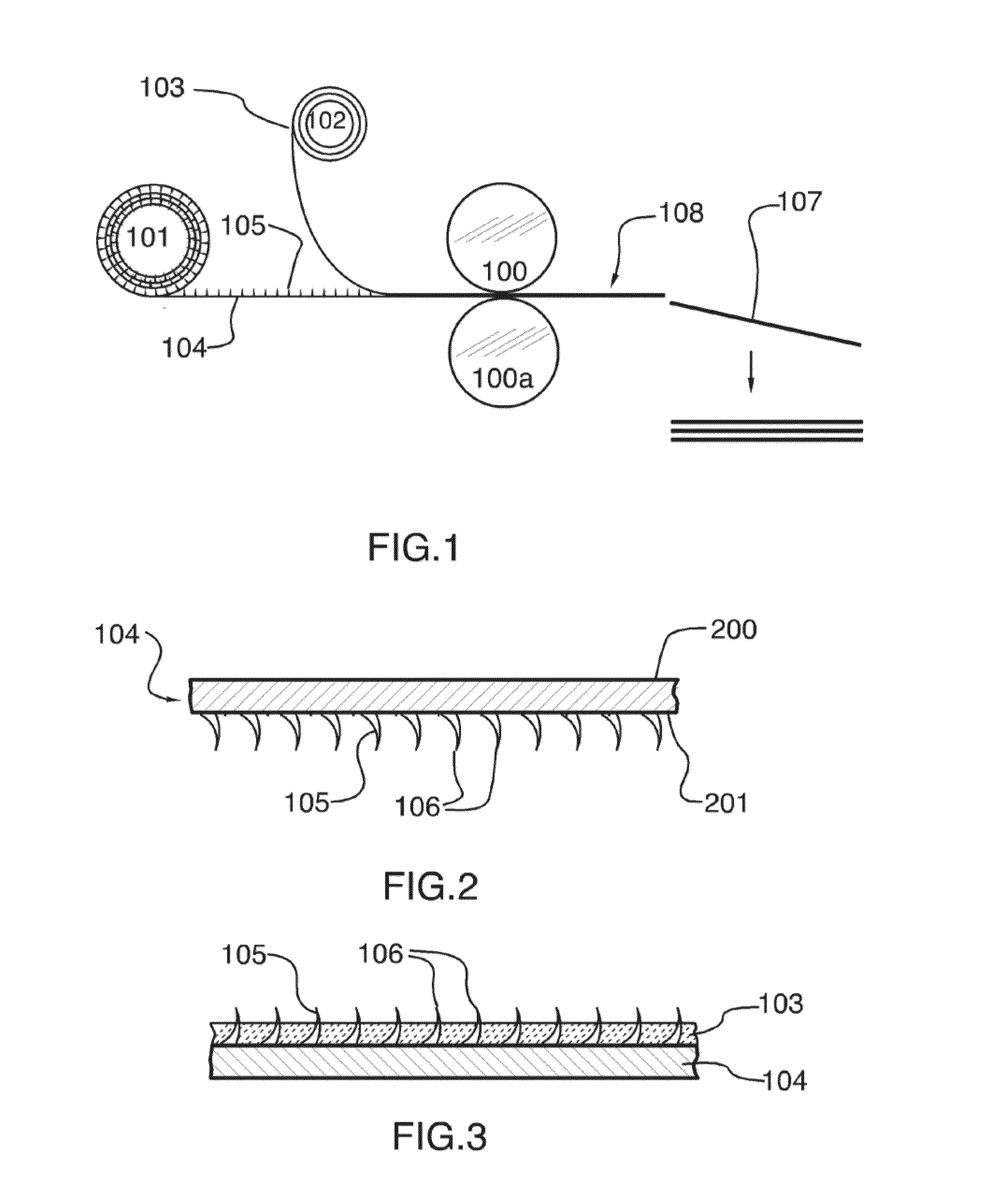
[0022]In the following description the word “clinch” (clinching, clinchable, clinched), is used to describe the act of bending over the exposed apex portion or “tip” of a pin- or nail-like structure that has pierced through two or more layers and extends therefrom. Clinching is common practice in the wood construction trade. Clinching is analogous to riveting in metal work, or to any other deformation of a fastener to prevent its easy withdrawal. The purpose of clinching is to impart greater cohesion between the two laminate layers that are so joined.

[0023]The terms “pointed structure” and “piercing structure” are used synonymously herein as a general term to describe any type of nail- or pin-like structure (or hooked or barbed structure) raised on the surface of a material (for embedding or piercing) that are capable of piercing and then penetrating the surface of a graphite foil. An appropriate choice of hardness of the material and shape and configuration of the piercing structur...


PUM

PropertyMeasurementUnit
Thicknessaaaaaaaaaa
Thicknessaaaaaaaaaa
Thicknessaaaaaaaaaa

Abstract

The present invention is a laminate sheet having two laminae. The first lamina is a relatively hard material having first and second surfaces. The first surface has a plurality of raised and generally pointed piercing structures, each structure having a tip. The second lamina is graphite foil material, which is mated to the relatively hard material, such that at least some of the piercing structures pierce the graphite foil material. In one embodiment, the first lamina has no perforations and is uniformly smooth. In another embodiment, the second surface also has a plurality of piercing structures and a third lamina comprising graphite foil is mated to the second surface.

Description

CROSS-REFERENCE TO RELATED APPLICATIONS[0001]This application is a U.S. continuation application under 35 U.S.C. §111(a) claiming priority under 35 U.S.C. §§120 and 365(c) to International Application No. PCT / CA2014 / 000579, filed Jul. 21, 2014, which claims the priority benefit of Canadian Patent Application No. 2,821,897, filed Jul. 26, 2013, the contents of which are incorporated by reference herein in their entirety for all intended purposes.FIELD OF THE INVENTION[0002]The present invention relates generally to laminated materials, and more particularly to laminated materials comprising at least one textured metal sheet layer bound to at least one graphite foil layer.BACKGROUND OF THE INVENTION[0003]There is a growing need for lighter, stiffer, cheaper structural materials, preferably with all three qualities, with which to make better products.[0004]Stainless steel laminated with graphite foil is a widely used material that has properties that make it suitable for many purposes,...

Claims


Application Information

Patent Timeline
IPC IPC(8): F16D65/00B32B15/18B32B9/00B32B9/04B32B3/30B32B7/08
CPCF16D65/0006B32B3/30B32B7/08B32B9/007B32B9/041B32B2605/00B32B2307/102B32B2307/536B32B2307/56B32B2307/54B32B2475/00B32B15/18F16J15/122F16D65/0971F16D2200/0021F16D2200/0034F16D2200/0052B32B3/266Y10T428/24339Y10T428/24529Y10T428/24545Y10T428/24289
Inventor ARBESMAN, RAYPHAM, NGHIMACKELVIE, WINSTON
Owner R A INVESTMENT MANAGEMENT S A R L
Why Eureka
Try Eureka