
Generation of power from rivers and the like

a technology of power generation and rivers, applied in the direction of propulsive elements, motors, propellers, etc., can solve the problems of damage to flora and fauna, high construction cost of dams and associated equipment, and equipment often sitting idle for long periods, etc., to and reduce the horizontal footprint of the apparatus

Inactive Publication Date: 2015-07-23
JONES PETER A
View PDF9 Cites 7 Cited by
  • Summary
  • Abstract
  • Description
  • Claims
  • Application Information

AI Technical Summary

Benefits of technology

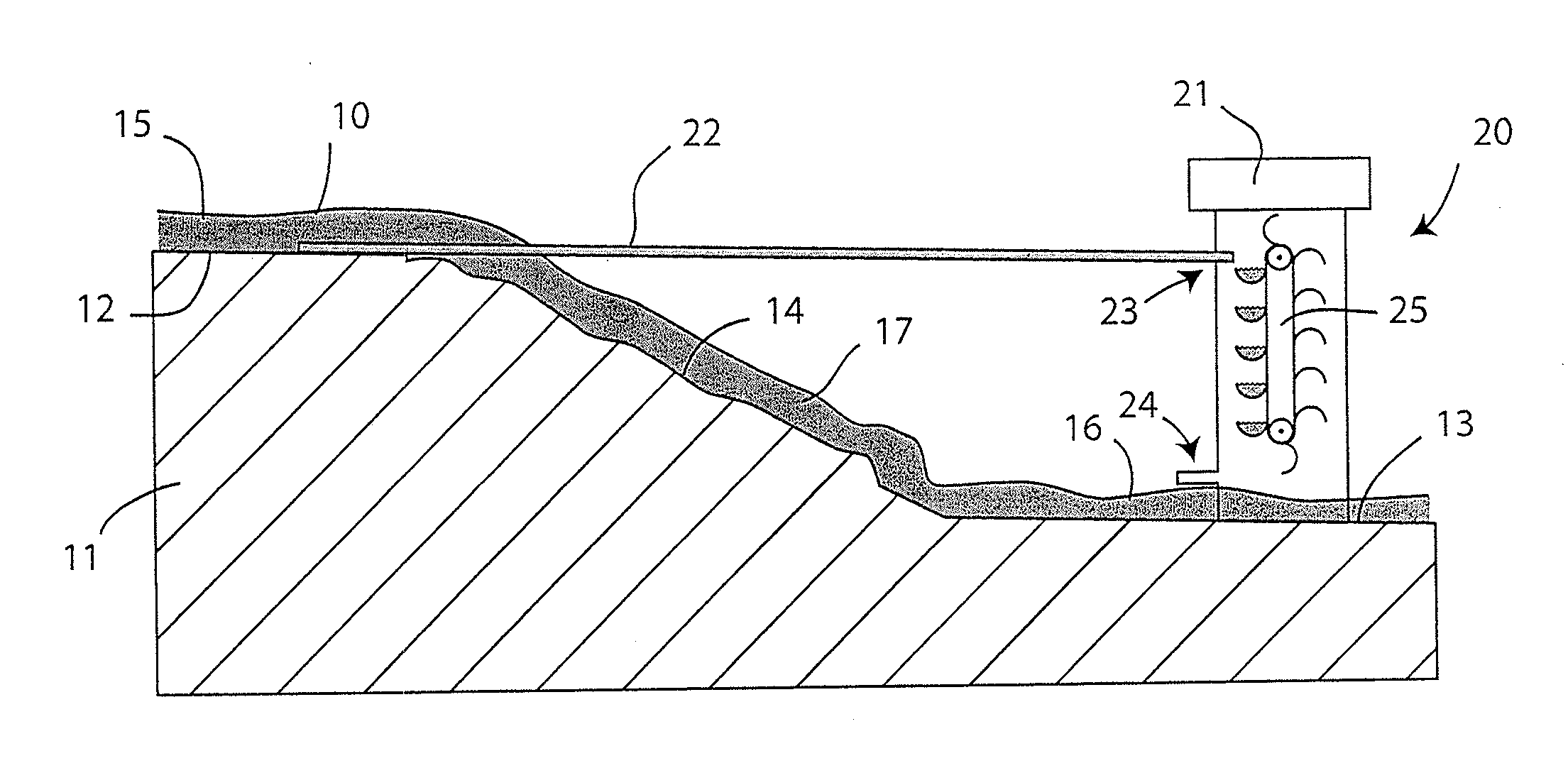
The present invention provides a method and apparatus for generating power from a renewable supply of water that has flowed from an elevated position to a lower position. The water is then forced to move, converting its gravity-based power into movement. The invention can be easily adapted to use different sources of water and does not require a significant investment of capital or damage to the environment. The apparatus has a small horizontal footprint and can generate power continuously over a full 24-hour period. Additionally, the invention utilizes a vertical elevator car design to reduce the horizontal footprint. Overall, the invention provides a reliable and flexible solution for generating energy from renewable water sources.

Problems solved by technology

Dams and the associated equipment are extremely expensive to build and the creation of reservoirs has involved the flooding of otherwise useful land and damage to flora and fauna.
Power generated from wind energy has become popular, but winds do not blow constantly, so the equipment often stands idle for long periods of time or can be damaged during storms.
Furthermore, wind turbines are frequently unpopular because they can be visually unappealing and noisy.
The generation of electricity from solar energy has also become popular, but can only be carried out during the day, or when clouds are absent, so again there are long periods when the equipment is idle.

Method used


Image

  • Generation of power from rivers and the like
  • Generation of power from rivers and the like
  • Generation of power from rivers and the like

Examples


Embodiment Construction

[0007]The present invention makes use of the weight of water and / or buoyancy (weight of water displaced) to generate energy, particularly in the form of electricity.

[0008]One exemplary embodiment of the present invention provides an apparatus for generating power from a source of water. The apparatus includes an upstanding structure adapted for support on ground adjacent to a renewable supply of water having an elevated region relative to the ground, the structure having a water inlet at a height no higher than the elevated region of the supply of water and a water outlet at a lower position than the inlet; a conduit for water extending between the elevated region of the water supply and the water inlet; and a gravity-operated energy converter supported by the structure that causes water to descend vertically between the horizontal levels of the inlet and the outlet while utilizing weight of the water thus descending to drive at least one movable element and thereby produce power.

[0...


PUM


Abstract

Exemplary embodiments of the invention provide an apparatus and method for generating power from a renewable source of environmental water. The apparatus includes an upstanding structure adapted for support on ground adjacent to the renewable source of water having an elevated region relative to the ground. A conduit for water extends between the elevated region of the water supply and a water inlet. A gravity-operated energy converter supported by the structure is provided that causes water to descend vertically between the inlet and an outlet adjacent the ground while utilizing the weight of the water thus descending to drive at least one movable element and thereby produce power. Additional energy may be provided from buoyancy by causing empty and inverted water containers to ascend through a column of water fed by the renewable source of water.

Description

BACKGROUND OF THE INVENTION[0001]1. Field of the Invention[0002]This invention relates to the generation of power from water flowing in rivers, streams, brooks, and other renewable sources of water. More particularly, the invention relates to the generation of electricity from such sources.[0003]2. Background of the Invention[0004]Power has been generated from rivers and other natural sources of flowing water for many generations. For example, water wheels have been used for powering machinery during the industrial revolution. However, such power generation has normally relied on the movement of the water, i.e. the momentum of the water as it flows generally horizontally along a water course such as a river bed. More recently, electricity has been generated by building dams across rivers to form reservoirs and feeding the water from the reservoirs through passages to turbines, but again use is made of the momentum of water moving through the passages generally at high speed and unde...

Claims


Application Information

Patent Timeline
Patent Type & Authority Applications(United States)
IPC IPC(8): F03B7/00F03B13/00
CPCF03B13/00F03B7/003F03B17/02F03B7/006Y02E10/20
Inventor JONES, PETER A.
Owner JONES PETER A
Learn More