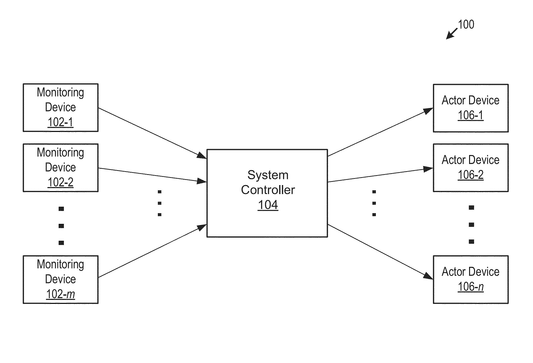
Automation System Comprising a Monitoring Device and Methods Therefor
a monitoring device and automatic system technology, applied in transmission systems, structural/machine measurement, transmission systems, etc., can solve the problems that home automation has only recently become practical, and achieve the effect of convenient manipulation and easy handling
- Summary
- Abstract
- Description
- Claims
- Application Information
AI Technical Summary
Benefits of technology
Problems solved by technology
Method used
Image
Examples
operational examples
[0168]As previously noted, the MD can be used as a control knob. That is, in some embodiments, turning the MD clockwise or counterclockwise about a predefined “first” axis of rotation (regardless of the MD's orientation in space) provides an indication of the amount / degree of desired change in the state of an actor (i.e., primary-channel information). In some embodiments, this functionality is implemented by a gyroscope and an accelerometer (see, e.g., FIG. 11: sensors 830-1 and 830-2, respectively). These sensors can also be used to alert of a malfunction, such as when a MD falls off of a wall-mounted base plate.
[0169]In the illustrative embodiments depicted in FIGS. 4A, 5A, 6A, and 7A, the first axis of rotation is axis A-A, B-B, C-C, D-D, respectively. A symmetry axis is typically, although not necessarily, selected as the first axis. As a consequence, for configurations that have a single symmetry axis, the symmetry axis is typically chosen as the first axis of rotation. Configu...
first example
[0179]A home automation system includes plural recessed overhead “smart” light bulbs, each of which transmits a radio beacon (all transmitting at the same power level) and actuation software and hardware suitable for responding to a request to increase or decrease the intensity of the light emitted from the bulb. The home automation system also includes a system controller and an MD, the latter capable of determining its rotation (as effected by a user) about a first axis, wherein such rotation relates to the amount by which the intensity of light from the bulb is to be increased or decreased. Rotation is determined using a gyroscope and accelerometer. The MD is also capable of measuring signal strength of the radio beacons to determine which of the plurality of overhead lights is nearest. Each beacon includes the address of its source, so that once the MD identifies the nearest smart bulb, it is capable of transmitting a message thereto, the message being a request for the bulb to ...
second example
[0180]A home automation system includes a system controller, an MD, a lamp with a “smart” light bulb as discussed above, and a smart television.
[0181]The MD includes a gyroscope and accelerometer and has configuration 410 depicted in FIGS. 4A and 4B. In a first orientation, the major surfaces of the MD are horizontal (like a coin lying flat on a table). In a second orientation, the MD is “on-edge,” wherein the major surfaces of the MD are oriented vertically (like a coin standing on its edge). The association and / or functionality of the MD is indicated by the aforementioned orientations. In the first orientation, the system controller designates the MD to function as a dimmer for the light bulb and in the second orientation to function as a loudness control for the television.
[0182]Once the MD is in either of these two orientations, rotation of the MD about a first axis, as reported via signal(s) from the MD, indicates the amount / degree of desired change in state of the actor. For e...
PUM
 Abstract
Description
Claims
Application Information
 - R&D
- Intellectual Property
- Life Sciences
- Materials
- Tech Scout
- Unparalleled Data Quality
- Higher Quality Content
- 60% Fewer Hallucinations
Browse by: Latest US Patents, China's latest patents, Technical Efficacy Thesaurus, Application Domain, Technology Topic, Popular Technical Reports.
© 2025 PatSnap. All rights reserved.Legal|Privacy policy|Modern Slavery Act Transparency Statement|Sitemap|About US| Contact US: help@patsnap.com


