
Colored, dynamic, and amplified safety film

a safety film and dynamic technology, applied in the field of optical elements, can solve the problems of inefficient printing method, low cost production of micro graphics, and inability to achieve large volume, and achieve the effects of improving visual identification features, enhancing security features, and rapid production of large-scal

Active Publication Date: 2015-07-16
SUZHOU UNIV +1
View PDF2 Cites 35 Cited by
  • Summary
  • Abstract
  • Description
  • Claims
  • Application Information

AI Technical Summary

Benefits of technology

The present invention provides an optical film with dynamic color micro graphic images on a color background. The film consists of two parts: a micro lens array and a micro-cavity interference structure. The micro-cavity interference structure generates background with high contrast and the micro lens array magnifies the micro graphics. The high-contrast images and background have the effect of improving optical image recognition. The invention meets the need for rapid production and enhances visual identification features over prior mono-color security elements. The technical effects of this invention include flexible and precise production of colored micro graphics, improved visual identification features, and a solution for colored viewing in optical security film device.

Problems solved by technology

However, with the popularity of laser holographic technology, the security effect of normal optical variable images gradually reduces.
Thus, at the current level of printing technology, 1-2 μm resolution micro graphics cannot be printed, so as not to have the accuracy for Moore amplification.
Meanwhile, inefficient printing method can hardly achieve large volume, low cost production of micro graphics.
The micro graphics made by normal nanostructures in CN101850680A, can only add background color through printing, which affects the contrast, so as to be difficult to satisfy the above requirements.

Method used


Image

  • Colored, dynamic, and amplified safety film
  • Colored, dynamic, and amplified safety film
  • Colored, dynamic, and amplified safety film

Examples


embodiment 1

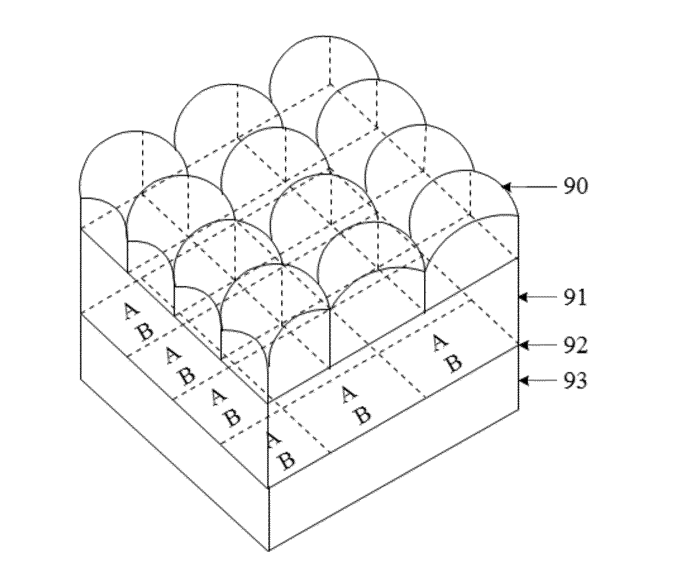
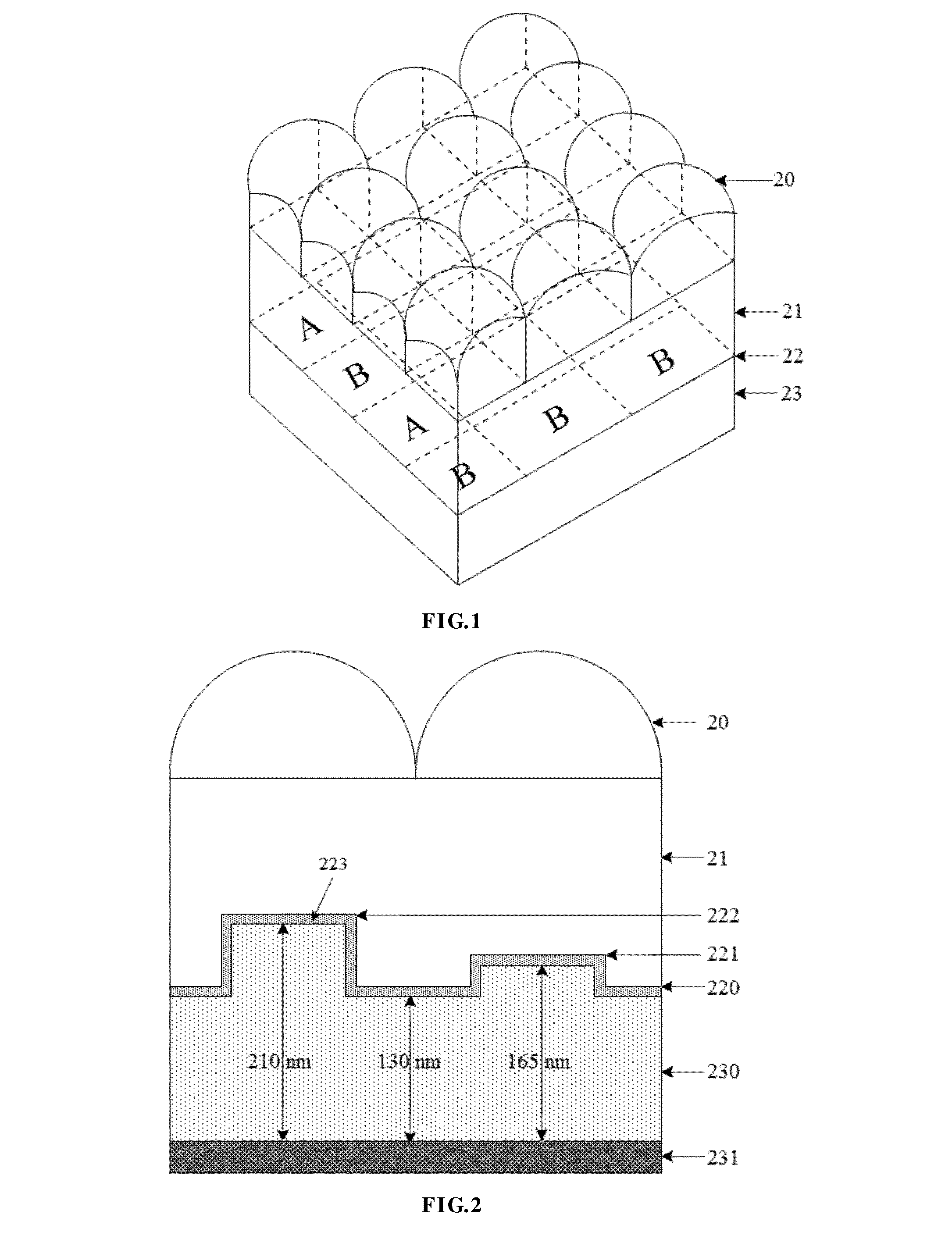
[0048]Imprinting a micro-cavity interference filter structure for two colors R, B on the micro graphic area corresponding to the micro lens array, as shown in FIG. 1, 20 is micro lens array layer, 21 is base substance layer, 22 is color micro graphic layer, 23 is color background lay. According to Moore amplified principle, it will form colored, dynamic, and amplified images.

[0049]In this embodiment, the sectional view of micro text pixel is shown in FIG. 2, in color micro graphic layer 22, 220 is the lower surface of base substance layer, 221 is horizontal plane where micro text B is on, 222 is horizontal plane where micro text A is on, 223 is semi-transparent and semi-reflective metal layer, which is a nickel film in this embodiment, 230 is a medium filling layer whose index of refraction is 1.5, 231 is a highly reflective metal film layer, which is a metal aluminum layer in this embodiment.

[0050]The micro-cavity interference structure consisted of color micro graphic layer and co...

embodiment 2

[0053]Imprinting a micro-cavity interference filter structure for three colors R, G, B on the micro graphic area corresponding to the micro lens array, as shown in FIG. 11, 20 is micro lens array layer, 21 is base substance layer, 22 is color micro graphic layer, in which there is a micro text array consisted of alphabets A, B, and C, 23 is colorless background lay. According to Moore amplified principle, it will form colored, dynamic, and amplified images.

[0054]In this embodiment, the sectional view is shown in FIG. 12, in color micro graphic layer 22, 220 is the lower surface of base substance layer, 621 is horizontal plane where micro text A is on, 622 is horizontal plane where micro text B is on, 623 is horizontal plane where micro text C is on, 223 is semi-transparent and semi-reflective metal layer, 230 is a medium filling layer whose index of refraction is 1.49, 231 is a total reflective metal layer.

[0055]Take micro-cavity interference structure for example, when the total re...

embodiment 3

[0057]Getting a micro graphic lay consisted of micro-cavity interference structure of set cavity thickness by imprinting technology, depositing a semi-transparent and semi-reflective metal layer, then filling the imprinting grooves with medium, and then depositing total reflective metal film layer, mono-color micro graphic layer and background layer will be obtained, with different colors of micro graphic layer and background layer. As shown in FIG. 14, imprinting micro graphic 821 with set depth on the lower surface of base substance, coating semi-transparent and semi-reflective metal layer 822, coating medium film layer 830, then coating a total reflective metal film layer 831, then coating a protective layer with medium if necessary. Thus, micro graphic layer and background layer will show mono but different color. Different colors can be selected, for example, dynamic amplified images of micro graphic use shorter wavelength (bluish), while background color uses longer wavelength...


PUM

PropertyMeasurementUnit
thicknessaaaaaaaaaa
thicknessaaaaaaaaaa
thicknessaaaaaaaaaa

Abstract

A colored, dynamic, and amplified security film includes a micro lens array layer, a base material layer, and a micro graphic layer. The layers meet the condition of Moore amplified imaging; the micro graphic layer is formed by a background area and a graphic area; the graphic area is distributed in the background area; the micro graphic layer includes a semi-transparent and semi-reflective metal layer, a medium layer, and a metal film layer successively from top to bottom; the metal film layer is of a planar structure; the thickness of the medium layer in the graphic area is greater than the thickness of the medium layer in the background area; and the thicknesses of semi-transparent and semi-reflective metal layers are consistent.

Description

FIELD OF THE INVENTION[0001]The present invention relates to optical element, and more particularly, to a security film which may show different color dynamic images in an amplified state. It is applied to the field of public security including brand security, cards, tickets, security documents, printing and packaging materials.BACKGROUND OF THE INVENTION[0002]As cards, tickets, brands of commodities and important documents relate to public security and / or important economic interests, new technologies, new materials and new concepts should be applied in this field to keep the anti-counterfeiting technology ahead of that of counterfeiters. Also, because cards, tickets, commodities are primarily circulated in the public places, one of the main requirements of the optical anti-counterfeiting technology is easy to be identified by the public. Optical variable images based on laser holographic technology is used for security identification on cards, passports, money, bonds, etc., for it...

Claims


Application Information

Patent Timeline
Patent Type & Authority Applications(United States)
IPC IPC(8): G02B3/00G02B5/28
CPCG02B5/18G02B3/0056G02B5/28G02B27/12G02B5/284B42D25/324B42D25/351B42D25/342B42D25/373
Inventor YE, YANCHEN, LINSENSHEN, SUZHOU, YUNZHOU, XIAOHONGHU, JINZHU, PENGFEIPU, DONGLINWEI, GUOJUN
Owner SUZHOU UNIV
Learn More