Receiver, transmitter, and communication method
a communication method and receiver technology, applied in the direction of digital transmission, code conversion, coding, etc., can solve the problems of difficult synchronous detection using this method for optical communication devices, the demodulation performance greatly deteriorates, and the fec decoding unit is difficult to correct errors
- Summary
- Abstract
- Description
- Claims
- Application Information
AI Technical Summary
Benefits of technology
Problems solved by technology
Method used
Image


Examples
first embodiment
[0039]This first embodiment is described by taking a case in which a low-density parity-check (LDPC) code is used as FEC as an example for the purpose of building a communication system that exhibits performance close to that of synchronous detection even when a phase slip occurs. Note that, in this first embodiment, the LDPC code is used as an example, but not only the LDPC code but also all error correction codes including a turbo code, a product code, a concatenated code, a Bose-Chaudhuri-Hocquenghem (BCH) code, a Reed-Solomon (RS) code, and a convolutional code are applicable in the same procedure.
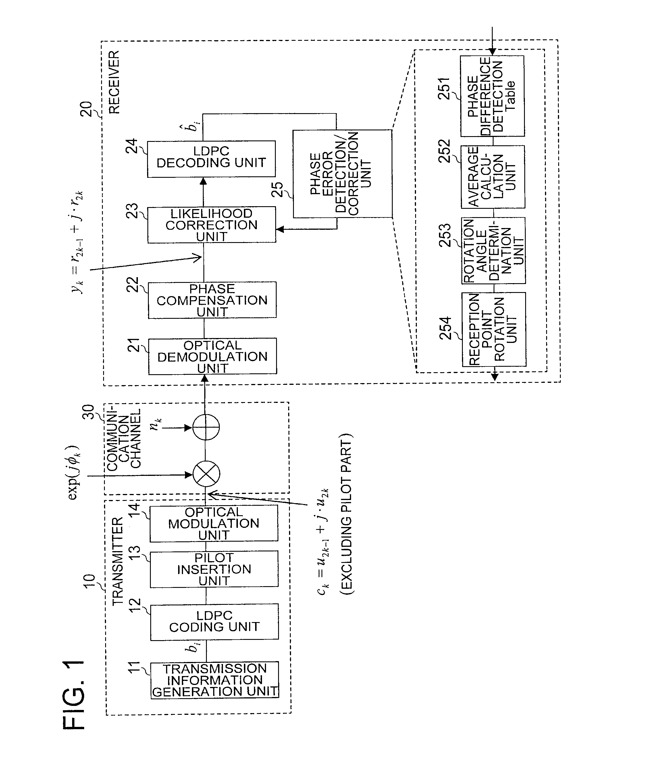
[0040]FIG. 1 is a configuration diagram of the communication system according to the first embodiment of the present invention. The communication system illustrated in FIG. 1 includes a transmitter 10, a receiver 20, and a communication channel 30 for connecting both to each other. Note that, FIG. 1 omits an ADC unit, an equalization unit, and a frame synchronization unit, which exist ...
second embodiment
[0109]In this second embodiment, a description is made of a specific example in which high-accuracy phase slip detection is performed in consideration of a slip probability caused in the phase compensation unit 22 illustrated in FIG. 1 described above. A probability that the phase slip occurs in the phase compensation unit 22 depends on the SNR, the nonlinear phase shift, and phase noise / wavelength offset of a light source. In this second embodiment, a developmental process of a phase slip is described by a Markov model.
[0110]In a 4-state Markov model, which is most simple, a phase φk obtained after the phase compensation in the k-th symbol depends only on the phase φk−1 of the previous symbol. Here, the phase φk is skπ / 2, and sk assumes one of the values 0, 1, 2, and 3 indicating the four states. Assuming that a transition probability from a state sk−1 to a state sk is expressed as:
[Math. 23]
Pr(sk|sk−1)=qsk, sk−1
a Markov state transition probability matrix Q is expressed as follow...
third embodiment
[0166]In this third embodiment, a description is made of a simultaneous estimation method for the phase slip and the transmission data in consideration of the slip probability of the phase compensation unit 22 by using soft-decision feedback information on the FEC. In the first and second embodiments described above, initial phase estimation is performed only in the position in which the known pilot signal is inserted, and the re-estimation is performed by using a hard-decision result of the decoding, which can improve the characteristics. The characteristics can be further improved when it is possible to simultaneously perform the estimation of a data sequence of the information symbol interval and the estimation of the phase slip state.
[0167]Therefore, a process including the following three steps A to C is executed in a method according to this third embodiment.
[0168](A) STEP 31: Simultaneous phase / data estimation processing performed by the likelihood correction unit 23
[0169](B)...
PUM
 Abstract
Description
Claims
Application Information
 - R&D
- Intellectual Property
- Life Sciences
- Materials
- Tech Scout
- Unparalleled Data Quality
- Higher Quality Content
- 60% Fewer Hallucinations
Browse by: Latest US Patents, China's latest patents, Technical Efficacy Thesaurus, Application Domain, Technology Topic, Popular Technical Reports.
© 2025 PatSnap. All rights reserved.Legal|Privacy policy|Modern Slavery Act Transparency Statement|Sitemap|About US| Contact US: help@patsnap.com