Portable Compound Battery System

Inactive Publication Date: 2015-07-09
FARADAY MOTOR
View PDF6 Cites 9 Cited by
  • Summary
  • Abstract
  • Description
  • Claims
  • Application Information

AI Technical Summary

Benefits of technology

The present invention is a portable compound battery system that can handle heavy load variations, such as electric vehicles, and provide high energy and power. It also improves energy efficiency and extends the life span of the entire battery system. The battery management module reduces management difficulties and lowers electric control costs, while the variable output power DC / DC converter allows for a flexible output power and maximum current limitation. This prevents excessive burden on the fixed high power battery and allows for replenishment any time. The user can also recharge the portable high energy battery set twice or utilize two portable high energy battery sets or even directly recharge the entire compound battery in order to completely replenish electric energy of the fixed high power battery set.

Problems solved by technology

Due to progression in the fields of power electronics and electronic technologies, the demands about sufficiently motor power output of electric vehicle are not major issues anymore; however, to replenish electric energy in electric vehicle becomes a critical challenge.
Basically, electric vehicles need to simultaneously satisfy requirements on range and power, thus with the fact that it is relatively challenging to use one single battery set to meet various feature demands at the same time, people have proposed a sort of compound battery system combining the features of high energy battery and high power battery to achieve this goal.
Its essential concept lies in that different types of batteries may exhibit different characteristics, and usually the high power density battery has less desirable energy density performance, and vice versa.
However, in practice, the bi-directional switch proposed in the above-said Patent may be unable to offer real-time output power distributions of the battery sets; that is, it may not resolve the issue of fast variations in power requirement of electric vehicles.
Although this design may be less complicated and practically implement said Patent's technology, the output power of the compound battery management system should reasonably respond to the average consumption power of the load, which may not be too low and can not be adjusted in accordance with the load requirement; consequently, the high power battery (in particular Lead-acid battery) may be adversely recharged with a high C rate thus leading to shortened life span in the high power battery.
Another point that needs to be compromised is that, the internal resistance of the high power battery may generate greater voltage drop due to high current from fast recharging, thus further causing heat consumption and undesirably reducing the recharging efficiency, so precious battery energy may be wasted.
This approach may provide certain improvements, but it should be noticed that, by simplifying and controlling vehicle load of continuous variations into two sections of output changes, electric energy replenishment to the high power battery set may still fluctuate due to vehicle load changes, so that the life extension in the high power battery set and its energy conversion efficiency may not be satisfactory.

Method used


Image

  • Portable Compound Battery System
  • Portable Compound Battery System
  • Portable Compound Battery System

Examples


Embodiment Construction

[0022]The aforementioned and other technical contents, aspects and effects in relation with the present invention can be clearly appreciated through the detailed descriptions concerning the preferred embodiments of the present invention in conjunction with the appended drawings.

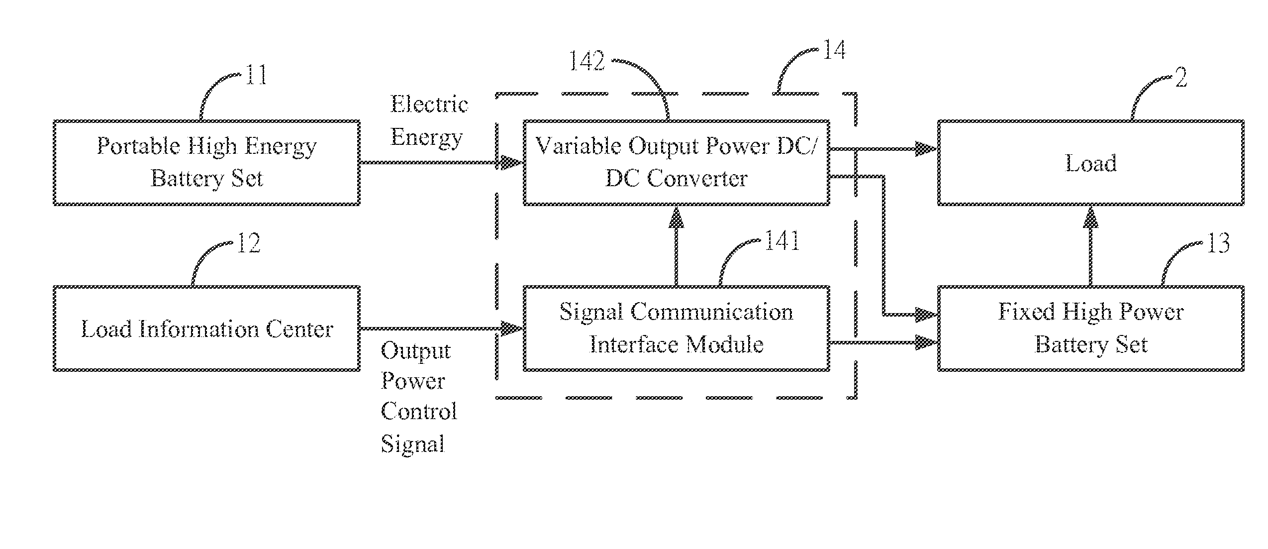
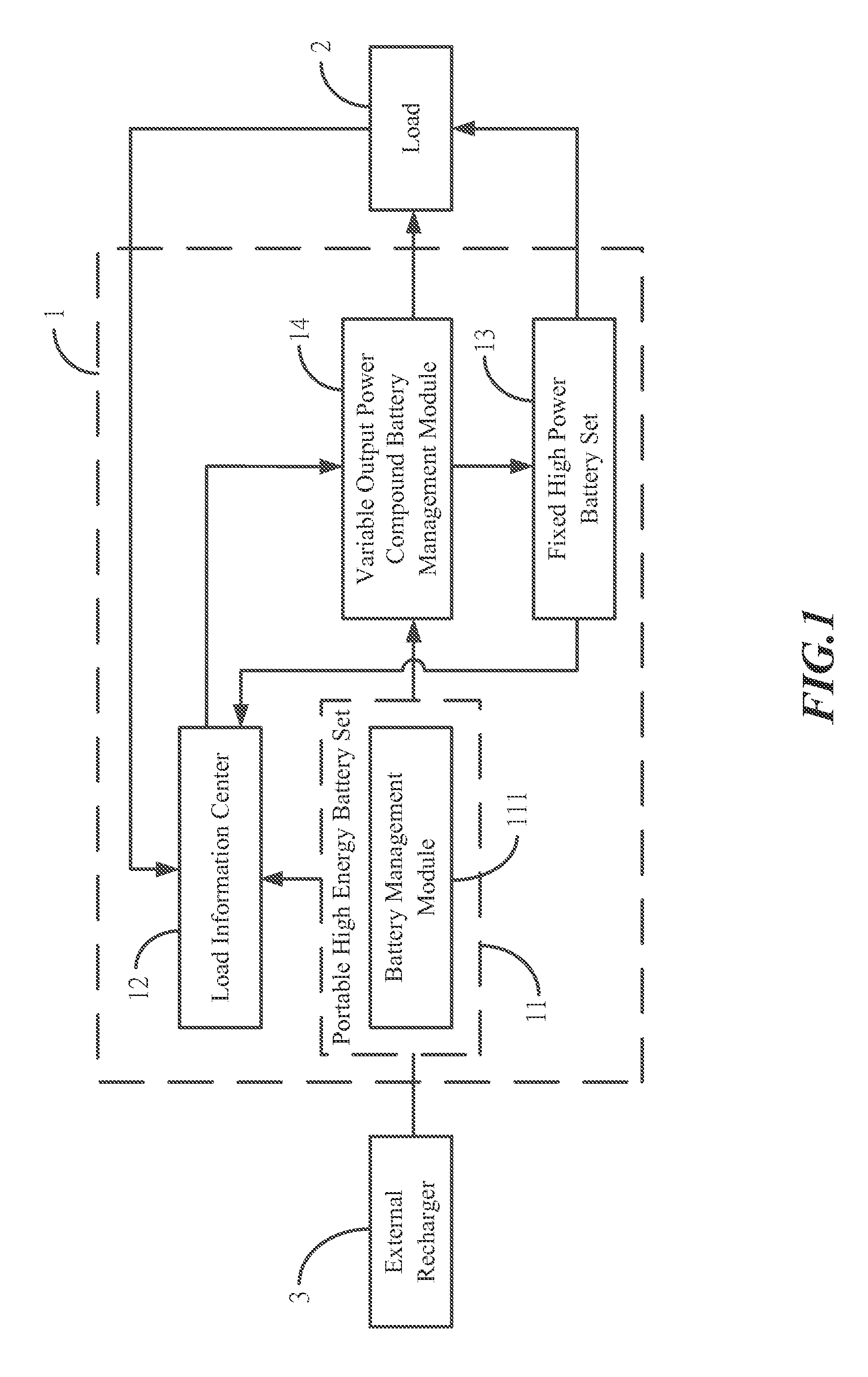
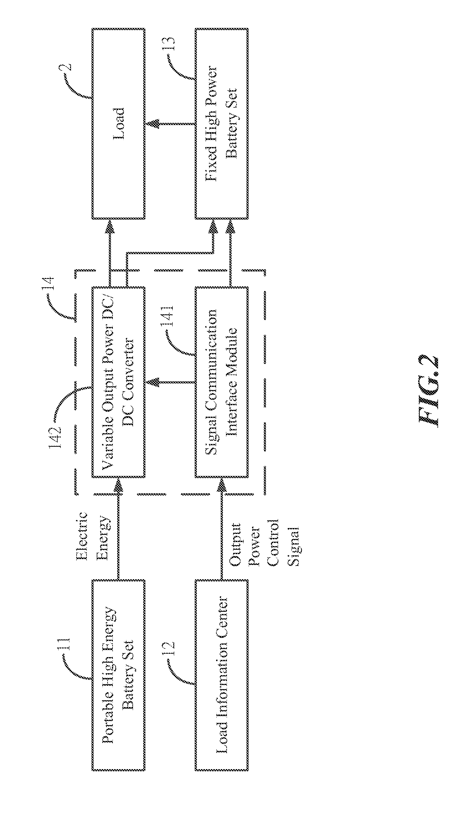
[0023]FIGS. 1 and 2 respectively show an overall architecture diagram for the portable compound battery system and an internal architecture diagram for the variable output power compound battery management module of the portable compound battery system in accordance with the present invention. The portable compound battery system 1 as shown in Figures comprises at least one or more portable high energy battery sets 11, a load information center 12, a fixed high power battery set 13 and a variable output power compound battery management module 14.

[0024]Herein the portable high energy battery sets 11 is internally configured with a battery management module 111 so as to reduce the difficulty in the management ...


PUM


Abstract

A portable compound battery system comprises at least one or more portable high energy battery sets, a load information center, a fixed high power battery set and a variable output power compound battery management module, wherein the portable high energy battery sets convert the output voltage by means of the variable output power compound battery management module including a variable output power DC / DC converter and then parallel with the fixed high power battery set. The system according to the present invention can determine the output power based on load requirements and overall battery system conditions so as to appropriately provide the electric energy that the load needs or replenish electric energy of the high power battery set. In addition, the portable high energy battery sets according to the present invention enable features in convenience and compactness, so it is possible to recharge using a battery recharger anytime and anywhere.

Description

BACKGROUND OF THE INVENTION[0001]1. Field of the Invention[0002]The present invention generally relates to a portable compound battery system; in particular, to an improved portable compound battery system applicable to various types of electric vehicles and capable of satisfying multiple requirements encompassing convenient energy replenishment, greater dynamic power supply as well as sufficient cruising distance by means of the energy supply system comprising the portable high energy battery set and the fixed power battery set.[0003]2. Description of Related Art[0004]Due to progression in the fields of power electronics and electronic technologies, the demands about sufficiently motor power output of electric vehicle are not major issues anymore; however, to replenish electric energy in electric vehicle becomes a critical challenge.[0005]Basically, electric vehicles need to simultaneously satisfy requirements on range and power, thus with the fact that it is relatively challenging...

Claims


Application Information

Patent Timeline
IPC IPC(8): H02J7/00
CPCH02J7/007H02J7/0063H02J7/0054H02J2007/0067H02J7/0013H02J7/342Y02T10/7072B60L53/80B60L58/30H02J7/0025Y02T10/70Y02T90/40Y02T90/14Y02T90/12
Inventor MA, BIN-YEN
Owner FARADAY MOTOR
Why Eureka
Try Eureka