Reinforced Foot for Agricultural Commodity Bin

a technology for agricultural commodities and bins, which is applied in the field of agricultural commodity bins with a reinforced foot or toe, can solve the problems of damage stopping at the location of the reinforcement, damage to the outer (plastic material) portions of the foot, and damage to the inside of the reinforcement, so as to achieve the effect of durable and/or, easy replacement, and additional stability and strength

Active Publication Date: 2015-07-09
WINTERBERG WILLIAM
View PDF6 Cites 3 Cited by
  • Summary
  • Abstract
  • Description
  • Claims
  • Application Information

AI Technical Summary

Benefits of technology

[0010]The present invention provides durable and resilient replacement feet (sometimes also referred to herein as toes) for use on agricultural commodity bins, and related methods of use, repair, and replacement. Embodiments of the feet or toes of the present invention are provided with reinforcing features, preferably but not necessarily made of metal, which resist damage from the harsh environments where the agricultural bins are used. The feet or toes of the present invention may be used to replace the rails on existing agricultural bins. For example, a single rail that extends along the underside of one side of an existing bin may be replaced by two such feet or toes, one at each end (corner) of one side of the bin. Similarly, a rail extending along the underside of the opposite side of the bin may be replaced by two additional feet or toes, so that one foot or toe may be provided in each corner of the bin.
[0011]According to embodiments of the present invention, reinforcement is provided at or near the outside edges and / or corners of the feet or toes. In some embodiments, the reinforcement is in the form of a removable bolt which may be screwed directly into the foot or toe, or engaged with a nut. Such a bolt assembly may be used to hold the foot or toe against the bottom of an agricultural bin, but it may also be provided only for reinforcement. In these embodiments, the bolt assembly itself (with nut, if provided) may be removed and replaced when damage occurs due to regular usage after wear and tear. This will reinforce the foot or toe, without necessarily replacing the entire foot.
[0012]In some embodiments, a recess is provided to receive the bolt head or a related structure so that it is generally flush with the bottom of the foot or toe when installed, preventing it from protruding out from the foot or toe assembly. The bolt head or related structure may be of any suitable shape, with the recess matching that shape. Normal wear and tear at the corner is expected to cause damage to the foot or toe itself, potentially causing exterior (e.g., metal, ceramic, rubber, or plastic material) portions of the foot to be dented, broken, and / or dislodged. However, the reinforcing assembly in the foot or toe is highly resistant to damage, such that even if some exterior portions of the foot may be damaged during normal use, that damage is stopped at the location of the reinforcement (such as the bolt head). The closer the reinforcing assembly is to an outside edge or corner of the foot, the less damage the foot will encounter before being stopped by the reinforcing assembly.
[0013]It is to be appreciated that multiple reinforcement assemblies or pieces of the types described herein may be provided in a single foot or toe of the present invention in order to provide increased resistance to damage. The reinforcement assemblies of the present invention are easily removed and replaced without necessarily replacing the foot or toe itself. However, even in the event of catastrophic damage to the foot or toe, replacement of the entire foot or toe with reinforcement assembly(ies) is a simple and inexpensive process allowing the agricultural bin to be placed back into use in a short time without compromising the integrity of the bin.
[0017]Some important features of embodiments of the present invention include: (1) a durable and / or resilient corner foot or toe for an agricultural storage bin, (2) the reinforcement structure(s) in the foot or toe being easily replaceable; (3) the foot or toe itself being replaceable without having to remove the entire storage bin base or rail, and / or (4) the foot or toe being reinforced at or near the corner. The reinforcement may be one or more bolt assemblies, or other or additional reinforcement pieces provided at various locations in the foot or toe. The reinforcement may also be one or more sturdy (preferably metallic) pieces may cover and attach to the entire foot or toe, or some portion of the foot or toe, such as the lower corner of the foot or toe. In a further alternative, foot or toe itself may be a metal structure having structural reinforcements, such as webbing, ribs, and cross pieces that lend additional stability and strength.
[0018]In an exemplary use, reinforced feet or toes of the present invention are installed underneath the corners of an agricultural bin, either before the bin is used or as replacements to existing rails. The bins are then placed into use where the reinforcement features of the feet or toes resist damage from wear and tear as the bin is raised, lowered, loaded, unloaded and transported from one location to another, adding longevity to the usefulness of the bin. In the event that a foot or toe is damaged, the reinforcement structure(s) or the foot or toe itself may be easily, inexpensively, and quickly removed and replaced without requiring the removal or replacement of any of the other structures or feet or toes, allowing the bin to be placed back into service in a short time.

Problems solved by technology

Normal wear and tear at the corner is expected to cause damage to the foot or toe itself, potentially causing exterior (e.g., metal, ceramic, rubber, or plastic material) portions of the foot to be dented, broken, and / or dislodged.
However, the reinforcing assembly in the foot or toe is highly resistant to damage, such that even if some exterior portions of the foot may be damaged during normal use, that damage is stopped at the location of the reinforcement (such as the bolt head).

Method used


Image

  • Reinforced Foot for Agricultural Commodity Bin
  • Reinforced Foot for Agricultural Commodity Bin
  • Reinforced Foot for Agricultural Commodity Bin

Examples


Embodiment Construction

[0033]Reference will now be made in detail to the illustrated embodiments of the invention. While the invention will be described in reference to the following detailed embodiments, it will be understood that the description is not intended to limit the invention to these embodiments. The invention is intended to cover alternatives, modifications, and equivalents that may be included within the spirit and scope of the invention as defined by the appended claims. Furthermore, in the following detailed description of the present invention, numerous specific details are set forth in order to provide a thorough understanding of the present invention. However, it will be readily apparent to one skilled in the art that the present invention may be practiced without these specific details.

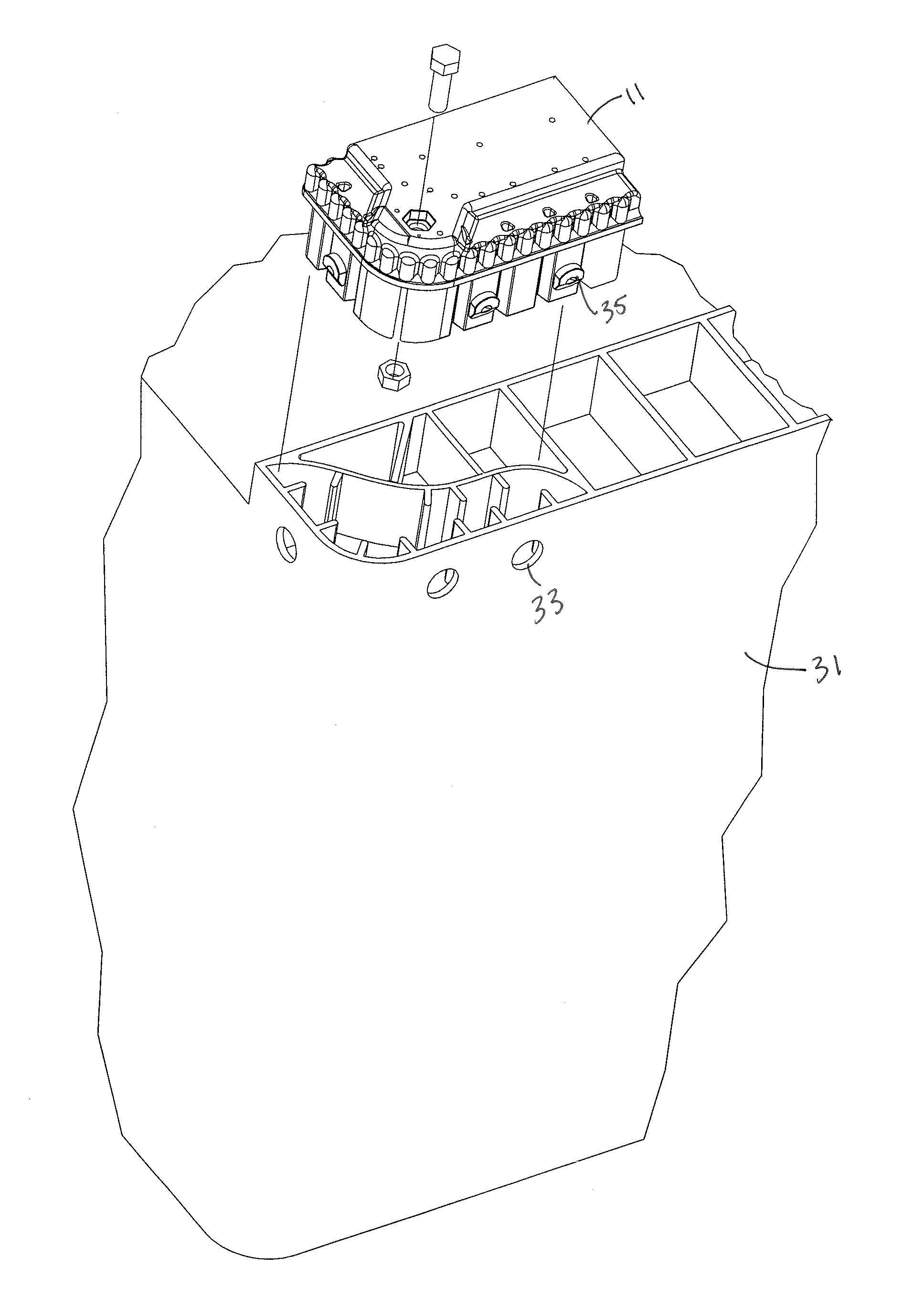
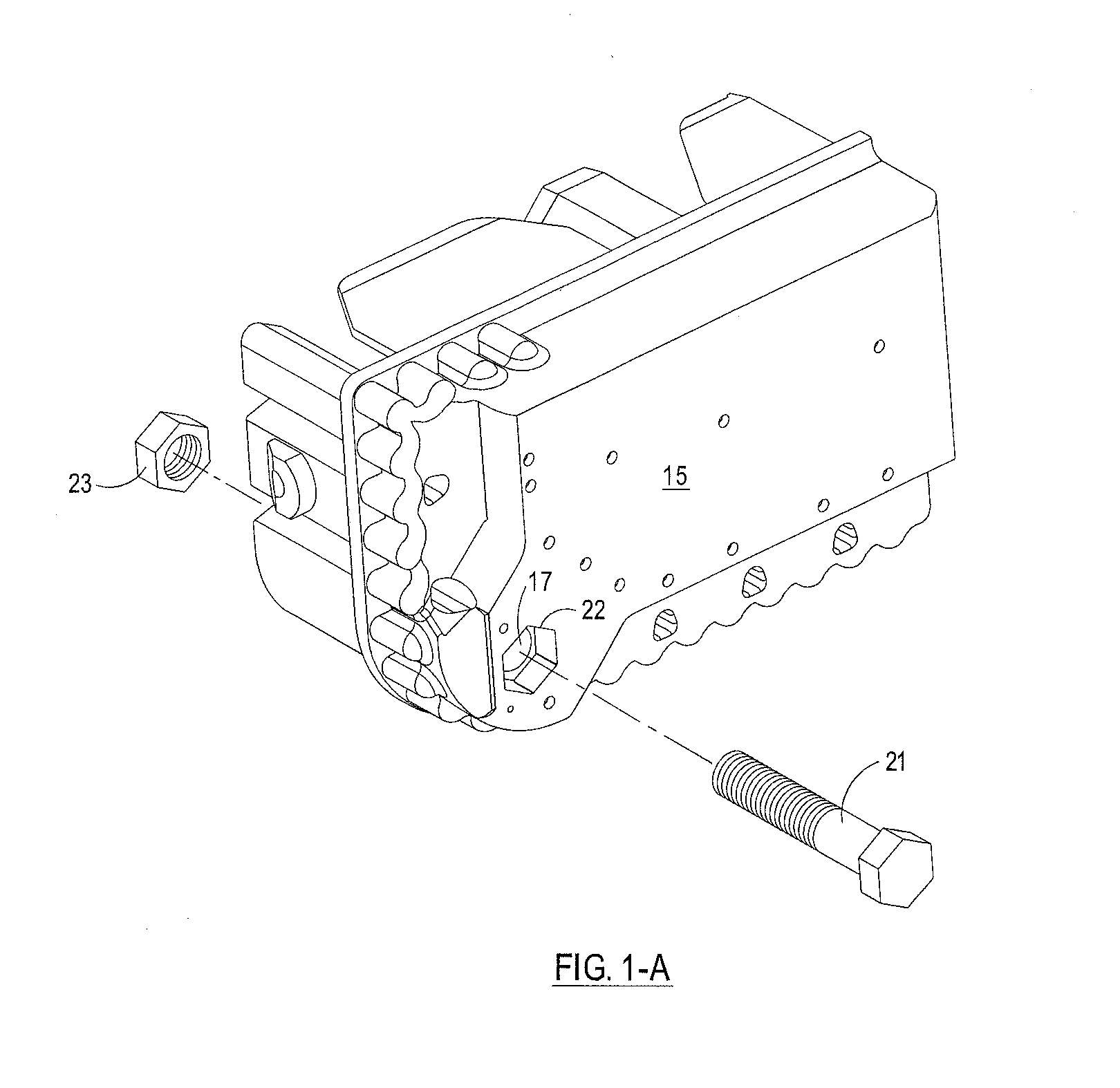
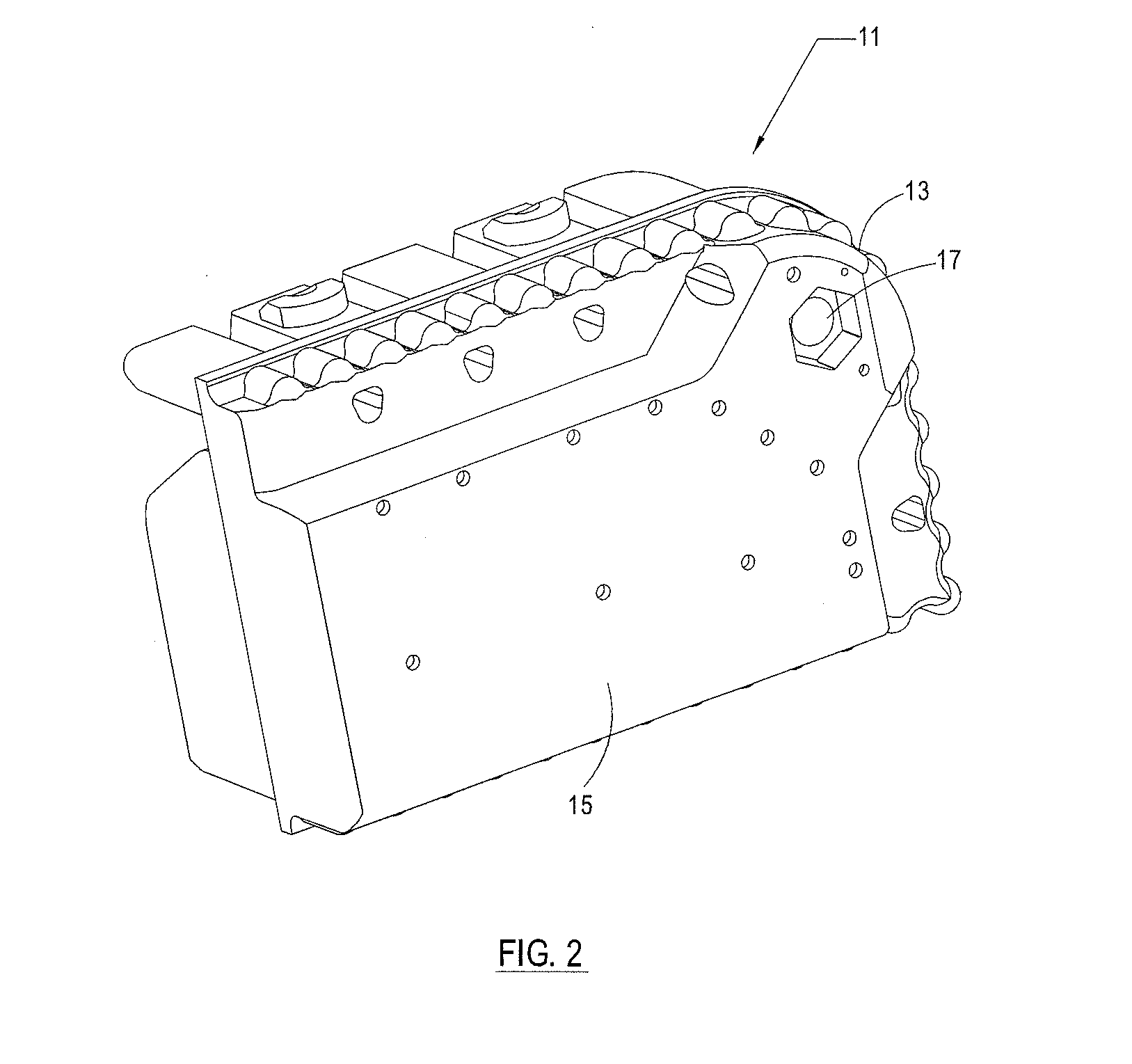
[0034]Referring to the drawings wherein like reference characters refer to the same or equivalent structure throughout the several views, and referring particularly to FIGS. 1 and 10, it is seen that the ...


PUM

PropertyMeasurementUnit
widthaaaaaaaaaa
widthaaaaaaaaaa
diameteraaaaaaaaaa

Abstract

Disclosed are structures for protecting the lower corners of containers used for storing and shipping agricultural commodities, and related methods of use. More particularly, removable reinforced feet or toes for protecting the lower corners of agricultural commodity bins are disclosed. The reinforced feet or toes are resistant to damage and may be easily removed, repaired and replaced. In embodiments of the invention, the feet or toes are provided with one or more removable reinforcement structures that may be removed and replaced by new structures when worn or damaged, without requiring removal of the feet or toes themselves.

Description

[0001]This application is a continuation of pending U.S. patent application Ser. No. 13 / 790,723, filed on Mar. 8, 2013, which claims the benefit of U.S. Provisional Application No. 61 / 650,422 filed on May 22, 2012, which is incorporated herein by this reference in its entirety.BACKGROUND OF THE INVENTION[0002]1. Field of the Invention[0003]The present invention relates to containers for harvesting and shipping agricultural commodities, and more particularly to removable reinforced feet or toes for agricultural commodity bins that are durable and resistant to damage and may be easily repaired or replaced, and related methods of use.[0004]2. Description of the Prior Art[0005]Reusable bins have long been in use for storing and transporting agricultural commodities. A typical agricultural storage bin includes a base and four sides, with an open top. The base of a typical bin is supported by a pair of rails which are provided in parallel along two opposite sides of the base. Some bins in...

Claims


Application Information

Patent Timeline
Patent Type & Authority Applications(United States)
IPC IPC(8): B65D90/12
CPCB65D90/12A01F25/14B65D19/18B65D2519/00034B65D2519/00069B65D2519/00129B65D2519/00174B65D2519/00273B65D2519/00288B65D2519/00323B65D2519/00338B65D2519/00442B65D2519/00572B65D2519/00621B65D2519/00666B65D2519/0096B65D2519/00975Y10T29/4973Y10T29/49826B23P11/00B23P6/00
Inventor WINTERBERG, WILLIAM
Owner WINTERBERG WILLIAM
Why Eureka
Try Eureka