Directional MEMS microphone and receiver device
- Summary
- Abstract
- Description
- Claims
- Application Information
AI Technical Summary
Benefits of technology
Problems solved by technology
Method used
Image
Examples
first embodiment
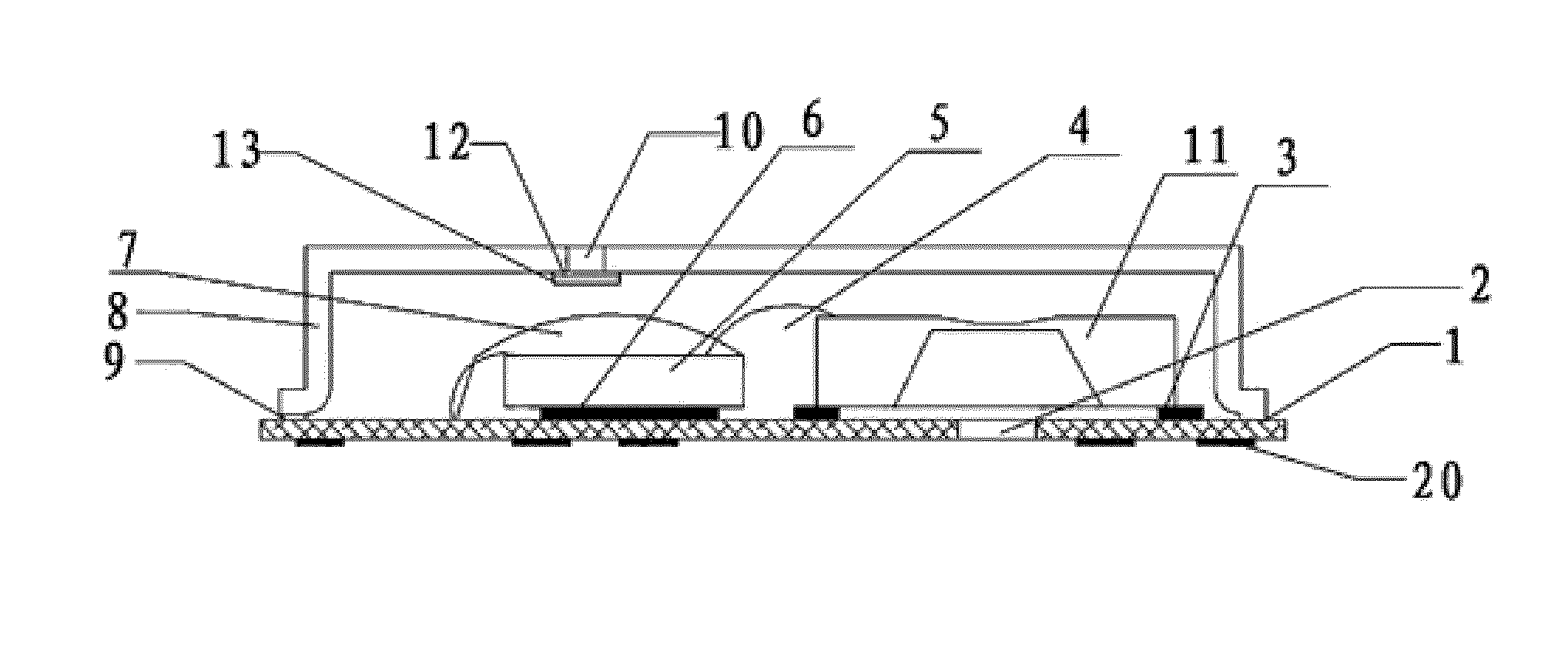
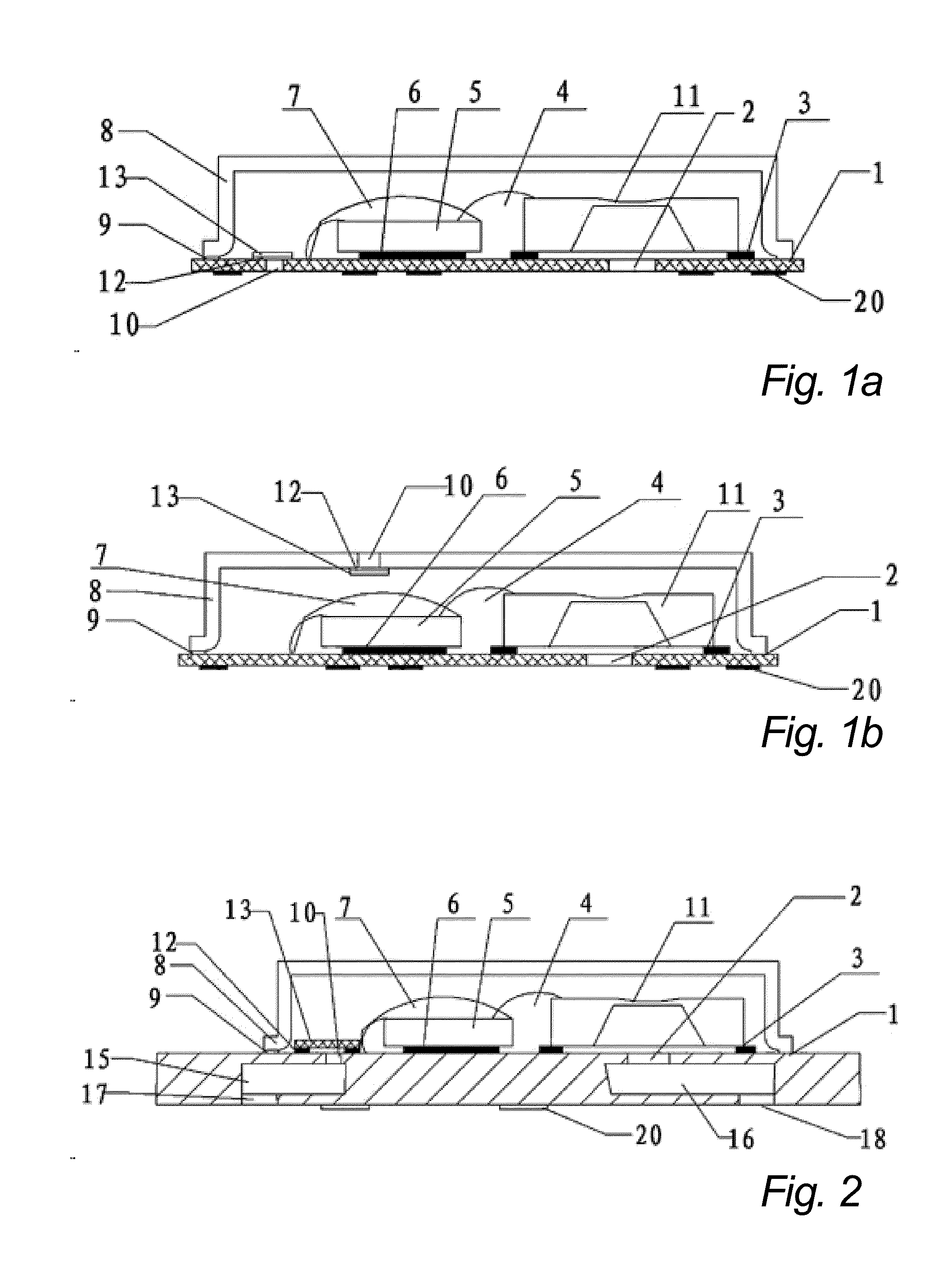
[0041]A first embodiment provides a directional MEMS microphone which comprises a microphone cover, a printed circuit board (PCB), a application specific integrated circuit (ASIC), a MEMS die, a diaphragm, a damping, a metal wire (s), at least two internal acoustic ports and external acoustic ports corresponding to the internal acoustic ports. The microphone cover is coupled to the PCB to form a housing. The ASIC chip and the MEMS die are attached to the PCB within the housing. The diaphragm is attached to the MEMS die. The ASIC chip, the MEMS die and the PCB are electrically interconnected by the metal wire (s). The damping is secured to cover either one of the internal acoustic ports or one of the external acoustic ports corresponding to the internal acoustic ports. The internal acoustic ports include a first internal acoustic port which is disposed on the PCB within the housing and is corresponded to the position of the diaphragm and a second internal acoustic port which is dispo...
second embodiment
[0049]In the present invention, taking the sound transmission channels formed respectively by two groups of internal acoustic ports, tuning cavities and external acoustic ports as an example, the directional MEMS microphone provided by the present invention is depicted. Referring to FIG. 2, the directional MEMS microphone comprises a PCB 1, a internal acoustic port 2, a metal wire (s) 4, an ASIC chip 5, a microphone cover 8, a internal acoustic 10, a MEMS die 11, a diaphragm and damping 13, a tuning cavity 15, a tuning cavity 16, a external acoustic port 17, and a external acoustic port 18.
[0050]A housing is formed by connecting the microphone cover 8 and the PCB 1. More particularly, the microphone cover 8 and the PCB 1 are secured together by the cover bonding adhesive 9, solder paste, or other bonding materials. The ASIC chip 5 and the MEMS die 11 are attached on the PCB 1 within the housing. More particularly, the ASIC chip 5 is attached to the PCB 1 by the ASIC bonding adhesive...
fourth embodiment
[0070]a directional MEMS microphone of the present invention is illustrated in FIG. 6. In the directional MEMS microphone provided by the embodiment, the tuning element 14 includes a wire board 14a, a body 14b and a tuning cover 14d. The body 14b is attached to the PCB 1 outside the housing via the wire board 14a by a adhesive 14c disposed between the body 14b and the wire board 14a, and a protective volume which holds the microphone cover 8 and the PCB 1 is formed by connecting the wire board 14a and the tuning cover 14d. The tuning cavity 16 is disposed inside the body 14b and the external acoustic port 18 is disposed on the body 14b. The tuning cavity 15 is disposed inside the tuning cover 14d and the external acoustic port 17 is disposed on the tuning cover 14d. The internal acoustic port 10 is disposed on the microphone cover 8. The protective volume which holds the microphone cover 8 and the PCB 1 is formed for shielding the directional MEMS microphone by connecting the wire b...
PUM
 Abstract
Description
Claims
Application Information
 - R&D
- Intellectual Property
- Life Sciences
- Materials
- Tech Scout
- Unparalleled Data Quality
- Higher Quality Content
- 60% Fewer Hallucinations
Browse by: Latest US Patents, China's latest patents, Technical Efficacy Thesaurus, Application Domain, Technology Topic, Popular Technical Reports.
© 2025 PatSnap. All rights reserved.Legal|Privacy policy|Modern Slavery Act Transparency Statement|Sitemap|About US| Contact US: help@patsnap.com


