
Circuit breaker

a circuit breaker and current carrying technology, applied in the field of circuit breakers, can solve the problems of not allowing the current carrying parts to exceed the temperature rise limit, the current rating desired is limited, and the forced cooling is impractical in the circuit breaker, so as to achieve reliable and cost-effective passive design, and increase heat dissipation

Active Publication Date: 2015-06-25
HITACHI ENERGY SWITZERLAND AG
View PDF4 Cites 1 Cited by
  • Summary
  • Abstract
  • Description
  • Claims
  • Application Information

AI Technical Summary

Benefits of technology

The patent is about improving a circuit breaker by making it better at dissipating heat at the points where the moving contact connects. This is done using a simple and reliable method that doesn't require extra components or extra cost.

Problems solved by technology

They are required to carry up to several thousand ampere of load current continuously, while not allowing the current carrying parts to exceed prescribed temperature rise limits.
Forced cooling is impractical in circuit breakers due to cost and reliability reasons.
However, the current rating desired is limited by the heat losses at the contact connection points.
Normal passive convection cooling can be inadequate to comply with the maximum allowed temperature rises in the contacts.

Method used


Image

  • Circuit breaker
  • Circuit breaker

Examples


Embodiment Construction

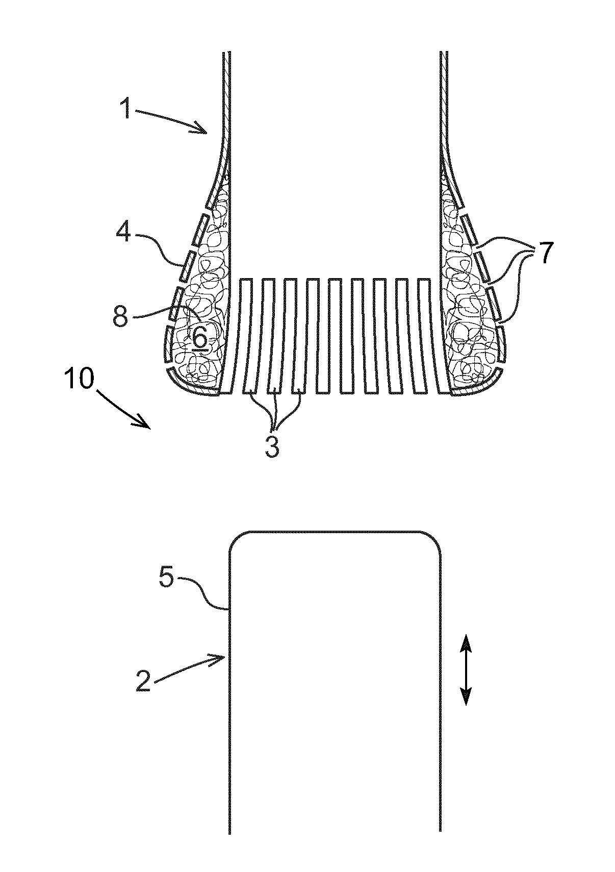
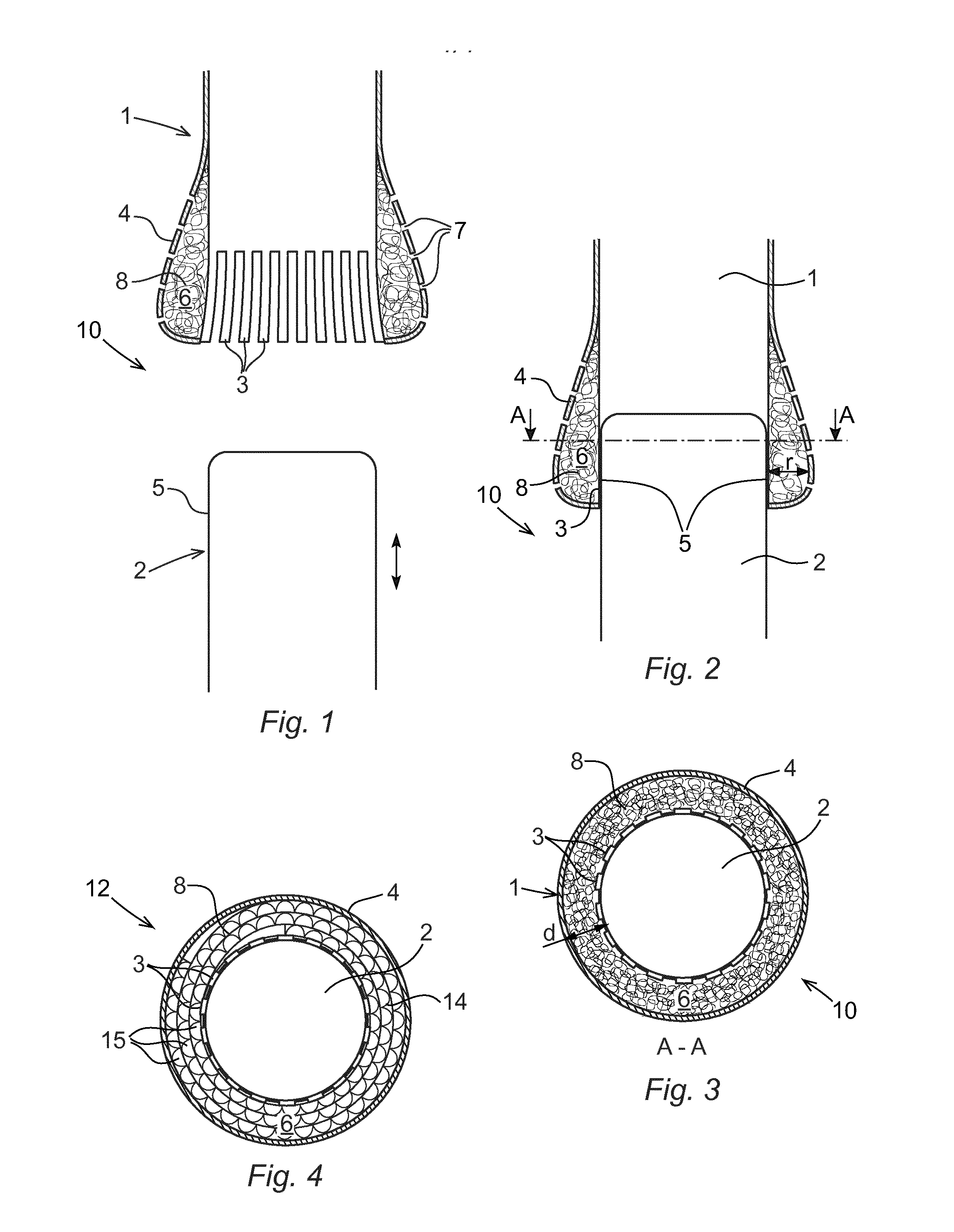
[0031]FIGS. 1-3 shows a circuit breaker 10 according to a first embodiment of the invention. FIG. 1 shows the circuit breaker 10 in an open position and FIG. 2 shows the circuit breaker 10 in a closed position. FIG. 3 shows a cross-section A-A through the circuit breaker 10 in the closed position. The circuit breaker 10 includes a first contact 1 and a second contact 2 movable relative each other between an open position, in which the contacts are at a distance from each other, as shown in FIG. 1, and a closed position, in which the contacts 1,2 are in electrical contact with each other, as shown in FIG. 2. Typically, one of the contacts is movable and the other contact is stationary. However, it is also possible that both contacts are movable. The first contact 1 includes one or more contact elements 3 adapted to be in contact with the second contact when the contacts are in the closed position. The contact elements are provided in one end of the first contact, and more particular ...


PUM


Abstract

A circuit breaker including a first and a second contact movable relative each other between an open position, in which the contacts are at a distance from each other, and a closed position, in which the contacts are in electrical contact with each other. The first contact includes one or more contact elements adapted to be in electrical contact with the second contact when the contacts are in the closed position, and a mesh made of metal arranged in thermal contact with the contact elements. The mesh is arranged to at least partly surround the contact elements to allow heat to conduct from the contact elements to the mesh.

Description

FIELD OF THE INVENTION[0001]The present invention relates to a circuit breaker including a first and a second contact movable relative each other between an open position, in which the contacts are at a distance from each other, and a closed position in which the contacts are in electrical contact with each other.PRIOR ART[0002]Generally, one of the contacts is stationary and the other contact is movable relative the stationary contact. However, in some applications both contacts are arranged movable relative each other. Typically, the contacts are surrounded by a dielectric medium, such as a gas or liquid. One of the contacts may include a plurality of contact elements, such as contact fingers, adapted to be in contact with the other contact when the contacts are in the closed position. The circuit breaker may also include an electrostatic shield assembly surrounding the contact elements.[0003]In live tank circuit-breakers (LTB) the contacts are housed in insulators at high voltage...

Claims


Application Information

Patent Timeline
Patent Type & Authority Applications(United States)
IPC IPC(8): H01H9/52H01H1/44H01H45/10H01H1/38
CPCH01H9/52H01H45/10H01H1/44H01H1/38H01H1/06H01H1/36H01H1/62H01H33/7046H01H33/7076
Inventor THOMAS, RICHARD
Owner HITACHI ENERGY SWITZERLAND AG
Learn More