System and method for compensating temperature gain variation in radiation detectors

Inactive Publication Date: 2015-06-25
GENERAL ELECTRIC CO
View PDF4 Cites 33 Cited by
  • Summary
  • Abstract
  • Description
  • Claims
  • Application Information

AI Technical Summary

Benefits of technology

The patent text provides methods for calibrating the gain of a radiation detector by measuring dark current at each detector element and determining the temperature corresponding to each measurement. A breakdown voltage or compensation for the temperature is determined, and a bias voltage is applied to each detector element based on the breakdown voltage or compensation. The applied bias voltage ensures a constant over voltage. Additionally, the patent text describes an imaging system that includes a detector panel with silicon photomultipliers that have a constant over voltage, and control circuitry to apply individual bias voltage to each microcell. The imaging system also includes image reconstruction and processing circuitry to generate images and a display workstation for display and analysis. The patent text also presents a method for determining changes in temperature at a radiation detector by measuring dark current and calculating the ratio of the dark current to a calibration dark current. The temperature difference between the calibration dark current and the measured dark current indicates the temperature at the detector. Overall, the patent text describes improved techniques for calibrating and measuring dark current and temperature in radiation detectors, which enhance the accuracy and reliability of the imaging process.

Problems solved by technology

One issue that may arise is that, in certain detector technologies where silicon photomultipliers are employed, the gain of the respective detection elements may be temperature dependent.
Such temperature related variation in gain may be problematic in imaging applications.

Method used


Image

  • System and method for compensating temperature gain variation in radiation detectors
  • System and method for compensating temperature gain variation in radiation detectors
  • System and method for compensating temperature gain variation in radiation detectors

Examples


Embodiment Construction

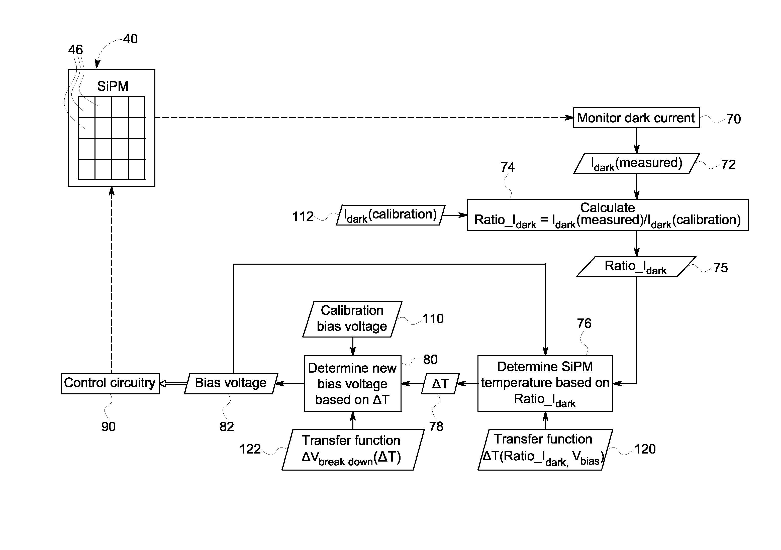
[0022]In accordance with the present disclosure, approaches for improving the usefulness of silicon photomultipliers (SiPM) in conjunction with radiation detection are described. As discussed herein, various radiation detection approaches exist that employ SiPMs incorporating an array of microcells (e.g., an avalanche photodiode (APD)) operating in Geiger mode. The breakdown voltage (Vbr) of the microcell, depends on the temperature. For example, the typical temperature coefficient is about +30 to +60 mV / ° C. for various APD structures. The SiPM works above the breakdown voltage in Geiger mode and the associated gain is proportional to the over voltage (Vov). As a result, the gain at a given microcell depends at least in part on temperature due to the dependence of breakdown voltage on temperature. For a typical over voltage of 2 V, this translates to a gain temperature coefficient of approximately −2% to −3% / ° C. However, knowledge of the amount of gain present in the SiPM at a giv...


PUM


Abstract

In accordance with the present approach, a dark current is measured for one or more detector elements and used to determine a gain or gain compensation for the respective detector elements. In certain embodiments, the dark current is used to determine a temperature for the respective detector element and the temperature is used to determine the gain or gain compensation. In other embodiments, the dark current is used to calculate the gain or gain compensation for the respective detector element without calculating an intermediate temperature value, such as via the use of a transfer function.

Description

BACKGROUND[0001]The subject matter disclosed herein relates to detection systems for use in imaging systems, such as X-ray based and nuclear medicine imaging systems.[0002]Diagnostic imaging technologies allow images of the internal structures of a patient to be obtained and may provide information about the function and integrity of the patient's internal structures. Diagnostic imaging systems may operate based on various physical principles, including the emission or transmission of radiation from the patient tissues. For example, X-ray based imaging systems may direct X-rays at a patient from some emission source toward a detector system disposed opposite the source across an imaged volume. Attenuation of the X-rays as they pass through the volume, and through any materials or tissues placed between the source and detector, may be determined and used to non-invasively form images of the interior regions of an imaged patient or object. Such attenuation information may be obtained ...

Claims


Application Information

Patent Timeline
IPC IPC(8): G01T7/00G01T1/24
CPCG01T7/005G01T1/247G01T1/248G01T1/208
Inventor DOLINSKY, SERGEI IVANOVICHMCDANIEL, DAVID LEO
Owner GENERAL ELECTRIC CO
Why Eureka
Try Eureka