Low Pressure Atomizing Injector

a low-pressure atomizing and injector technology, applied in the direction of engines, mechanical equipment, machines/engines, etc., can solve the problems of low injection pressure, limited injection pressure, and sensitive working fluid atomization in exhaust gas processing systems, so as to improve atomization performance and accurately measure injection pressure. , the effect of high flow velocity

Active Publication Date: 2015-06-25
QI BAOHUA
View PDF8 Cites 6 Cited by
  • Summary
  • Abstract
  • Description
  • Claims
  • Application Information

AI Technical Summary

Benefits of technology

[0016]According to one embodiment of the present invention, an injector with a pre-atomizing chamber and a swirl chamber is provided. In this injector, the pre-atomizing chamber is enclosed by an upper injector body with a first exit nozzle and an atomization element, which is used for creating a swirling flow in the swirl chamber. Through the first exit nozzle, a high flow velocity can be obtained at low injection pressure, and in the pre-atomizing chamber, the impingement of the working fluid on the atomization element further improves atomization performance. Through the pre-atomizing chamber and the atomization element, the working fluid then enters the swirl chamber and is further released to a working environment via a second exit nozzle on the bottom of the swirl chamber. In the injector, a flow-back is not necessary, while the injector can be fit in an adaptor, which may have coolant circling inside for carrying heat away. Without effects of the flow-back, a pressure sensor can be positioned upstream from the injector to accurately measure the injection pressure, and thereby flow rate control can be accurately compensated.
[0017]According to another embodiment of the present invention, an injector with a control valve positioned through an atomization element is provided. In the injector, a swirl chamber is enclosed by the atomization element and an injector body, and an exit nozzle is positioned at the bottom of the swirl chamber. At a closed position, i.e., when the injector is de-energized, a front end portion of the control valve is in contact with a valve seat at the bottom of the swirl chamber, blocking working fluid from flowing out. After the injector is energized, the control valve is lifted up, contacting the front end portion to a valve seat at the bottom of the atomization element, blocking working fluid from flowing through a bore in the atomization element, through which the control valve is positioned, and forcing working fluid entering the swirl chamber through swirling grooves of the atomization element. The result swirling flow is then released to a working environment through the exit nozzle. As the one according to the first embodiment of the present invention, this injector has no flow-back, and thereby flow rate can be controlled accurately with sensing values obtained from a pressure sensor positioned upstream from the injector.

Problems solved by technology

In exhaust gas processing systems, however, injection pressure is limited.
Though injection pressure is low, exhaust gas processing systems are sensitive to working fluid atomization.
In a DPF system, poor atomization causes delay in fuel oxidation in catalyst and fuel carbonization (coking), which may block doser nozzles and deteriorate temperature control performance, while in a SCR system, large droplet of DEF lowers deNOx efficiency and increases chances of urea crystallization, which may block injectors, catalysts, and even exhaust passages.
The compressed air lowers exhaust temperature, which is critical to reactions in the exhaust gas processing system, resulting in evaporation issues, poor thermolysis, and higher energy cost, and evaporates working fluid in the mixer in which the working fluid mixes with the compressed air, causing deposit and crystallization therein.
Additionally, compressed air in the mixer varies pressure drop across the injector when a metering injector is used, introducing errors in flow rate control.
Cycling the working fluid through the injector carries heat away therefrom, however, heating working fluid may cause fluid quality issues, since some working fluid deteriorates at high temperature, for example, deterioration of DEF starts to accelerate at a temperature higher than 50° C., while working fluid cycling downstream from the pressure sensor causes variations in pressure difference across the injector nozzle undetected, resulting in errors in flow rate control.

Method used


Image

  • Low Pressure Atomizing Injector
  • Low Pressure Atomizing Injector
  • Low Pressure Atomizing Injector

Examples


Embodiment Construction

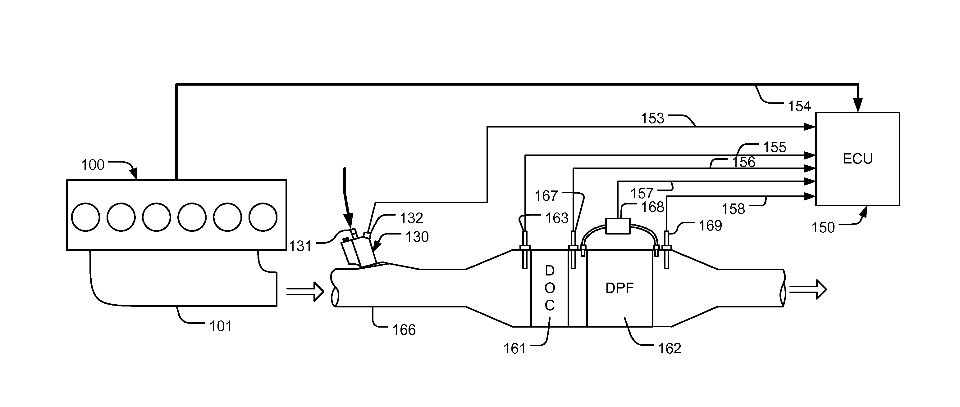
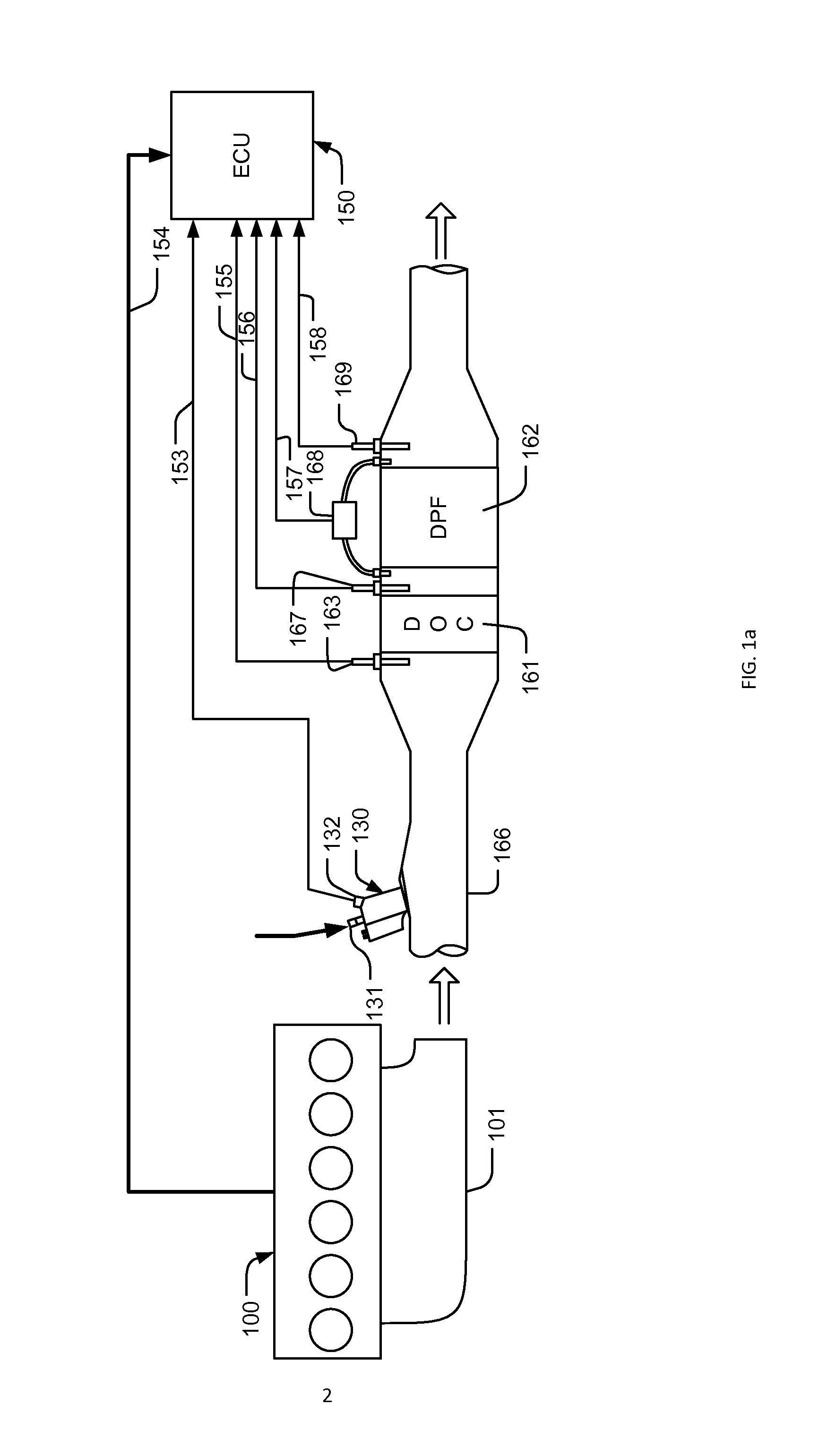
[0026]Referring to FIG. 1a, in a diesel engine DPF system, an engine 100 with its exhaust manifold fluidly coupled to an exhaust passage 166, which is then fluidly connected to a catalyst package having a DOC 161 and a DPF 162 contained. A fuel injection device 130 with an injector 131 enclosed in an adaptor, which may have coolant cycling inside for carrying heat away, is used for providing fuel in regenerating the DPF, when the PM (Particulate Matter) collected therein is above a certain level. The injector 131 is controlled by an ECU (Engine Control Unit) 150 through signal lines 153 connected to a connection port 132, while sensing signals are obtained from the engine 100 by the ECU 150 through signal lines 154. Upstream from the DOC 161, a temperature sensor 163, which is electrically connected to the ECU 150 through signal lines 155, is used for measuring exhaust gas temperature at the inlet of the DOC 161, and temperature sensing signals obtained from two temperature sensors ...


PUM


Abstract

An injector for delivering a working fluid into a working environment is disclosed. According to one embodiment of the present invention, the injector includes a pre-metering chamber and a swirl chamber. A high velocity partially atomized flow is produced in the pre-metering chamber through a first exit nozzle after impinging on an atomization element, and then a swirling flow is created in the swirl chamber with the atomization element. When the swirling flow is released through a second exit nozzle, atomization can be achieved at low injector pressure with centrifugal force and shearing of the working fluid. In another embodiment, the injector includes a swirl chamber and an atomization element with a bore, through which a control valve is positioned. The control valve forces a working fluid flow through the atomization element when the injector is energized to create a swirling flow. No flow-back is required for the injectors.

Description

TECHNICAL FIELD OF THE INVENTION[0001]This present application claims priority from U.S. provisional application No. 61 / 920,424 having the same title as the present invention and filed on Dec. 23, 2013.CROSS-REFERENCE TO RELATED APPLICATIONS[0002]Not ApplicableSTATEMENT REGARDING FEDERALLY SPONSORED RESEARCH OR DEVELOPMENT[0003]Not ApplicableREFERENCE TO SEQUENCE LISTING, A TABLE, OR A COMPUTER PROGRAM LISTING COMPACT DISC APPENDIX[0004]Not Applicable[0005]The present invention relates to a working fluid injection device, and more specifically, to an injection device for controlling a flow rate of a working fluid and atomizing the working fluid.BACKGROUND OF THE INVENTION[0006]In an engine system, especially in a compression-ignition engine, such as a diesel engine, injectors are used in in engine cylinders and exhaust gas processing systems. In both applications, the main functions of the injector include controlling a flow rate of a working fluid and atomizing the working fluid.[0...

Claims


Application Information

Patent Timeline
Patent Type & Authority Applications(United States)
IPC IPC(8): F01N3/28F01N3/20
CPCF01N3/20F01N3/28F01N3/2066F01N2610/02F01N2610/1453Y02T10/12
Inventor QI, BAOHUA
Owner QI BAOHUA
Why Eureka
Try Eureka