


Quick Research
Generate reliable direction feasibility study reports for your R&D in just a few steps.

Technical Q&A
Discover and master advanced knowledge NOW. Basics, ideas, possibilities, all at once.

Find Solutions
As an expert in R&D theories, this can generate solutions to your technical problems instantly.

Evaluate Feasibility
Analyze your overall solution with one click, know your potential R&D risks in advance.

Monitor Landscape
Get weekly tech updates, stay abreast of the latest tech innovations and key insights.
Head mounted display device
a display device and display device technology, applied in the direction of static indicating devices, instruments, portable computer details, etc., can solve the problems of user feeling strangeness, difficult to have the feeling of strangeness, and outside scenery of virtual image as imaged image is provided with delay
- Summary
- Abstract
- Description
- Claims
- Application Information
AI Technical Summary
Benefits of technology
Problems solved by technology
Method used
Image


Examples
embodiment
A. Embodiment
A-1. Configuration of Head Mounted Display Device:
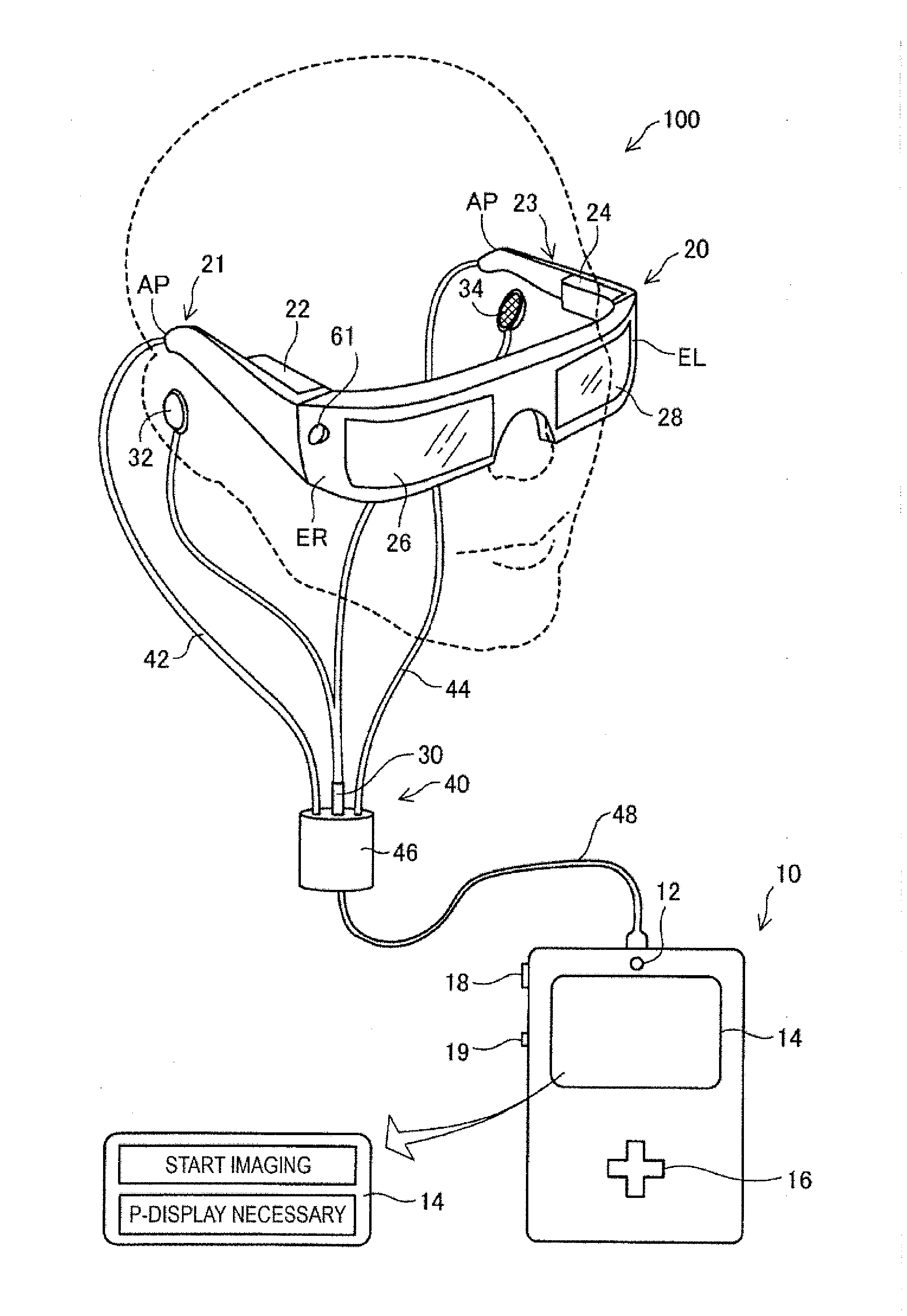
[0033]FIG. 1 is an explanatory diagram showing a schematic configuration of a head mounted display device in one embodiment of the invention. The head mounted display device 100 is a display device worn on a head and also called a head mounted display (hereinafter, “head mounted display 100”). The head mounted display 100 of the embodiment is an optically-transmissive head mounted display device that enables visual recognition of a virtual image and direct visual recognition of outside scenery.
[0034]The head mounted display 100 includes an image display unit 20 allows the user to visually recognize a virtual image when worn on a head of a user, and a control unit (controller) 10 that controls the image display unit 20.
[0035]The image display unit 20 is a wearable unit worn on the head of the user and has a spectacle shape in the embodiment. The image display unit 20 includes a right holding part 21, a right display drive...
modified example 1
[0074]In the above described embodiment, the configuration of the head mounted display is exemplified. However, the configuration of the head mounted display may be arbitrarily determined without departing from the scope of the invention. For example, addition, deletion, conversion, etc. of the respective configuration parts may be made.
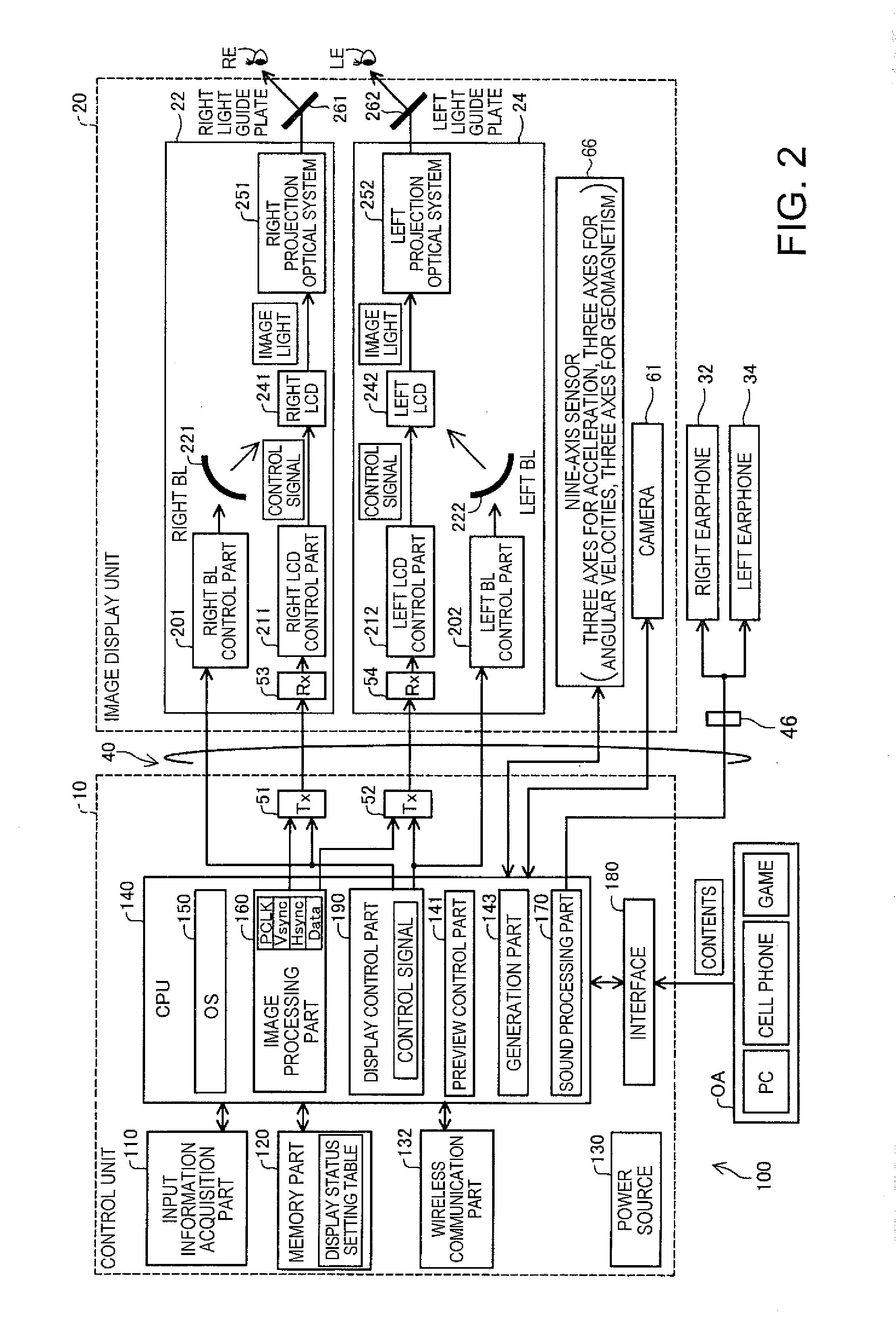
[0075]The assignment of the component elements to the control unit and the image display unit in the above described embodiment is just an example, and various forms may be employed. For example, the forms are as follows: (i) a form in which the processing functions of the CPU, the memory, etc. are provided in the control unit and only the display function is provided in the image display unit; (ii) a form in which the processing functions of the CPU, the memory, etc. are provided in both the control unit and the image display unit; (iii) a form in which the control unit and the image display unit are integrated (e.g., a form that functions as a spec...
PUM
 Abstract
Description
Claims
Application Information
 - R&D Engineer
- R&D Manager
- IP Professional
- Industry Leading Data Capabilities
- Powerful AI technology
- Patent DNA Extraction
Browse by: Latest US Patents, China's latest patents, Technical Efficacy Thesaurus, Application Domain, Technology Topic, Popular Technical Reports.
© 2024 PatSnap. All rights reserved.Legal|Privacy policy|Modern Slavery Act Transparency Statement|Sitemap|About US| Contact US: help@patsnap.com