
Hydraulic rotating equipment, and working machine provided with this hydraulic rotating equipment

Active Publication Date: 2015-06-18
HITACHI CONSTR MASCH CO LTD
View PDF4 Cites 0 Cited by
  • Summary
  • Abstract
  • Description
  • Claims
  • Application Information

AI Technical Summary

Benefits of technology

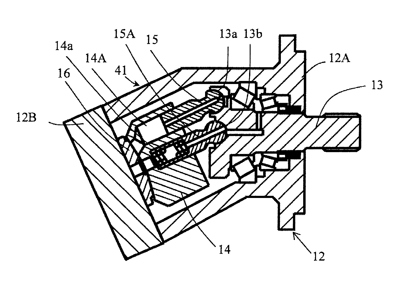
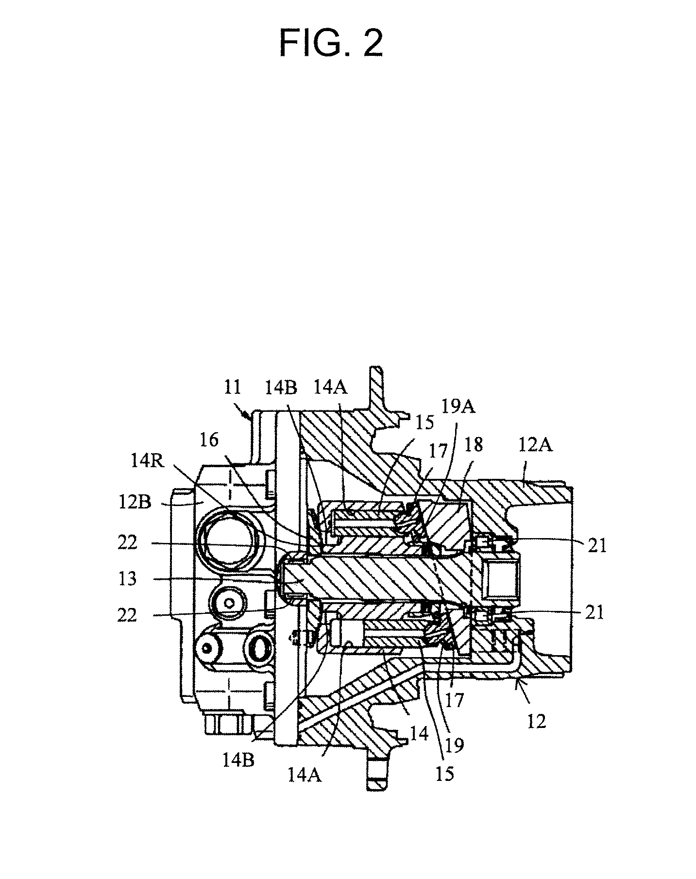
The present invention provides a hydraulic rotating equipment and a working machine with the same that can reduce the torque loss associated with rotation of the cylinder block. By arranging a sliding contact member on the periphery of the seal land of the valve plate, the slide contact surfaces of the valve plate and cylinder block can be protected while decreasing the slide contact area between them. This configuration can alleviate seizure that occurs on the slide contact surfaces and reduces torque loss.

Problems solved by technology

In particular, the hydraulic oil leaks in a large amount from the high-pressure port.
Therefore, the friction force that the cylinder block receives from the slide contact surface of the valve plate during rotation increases, leading to a concern that a torque loss may increase in association with rotation of the cylinder block.

Method used


Image

  • Hydraulic rotating equipment, and working machine provided with this hydraulic rotating equipment
  • Hydraulic rotating equipment, and working machine provided with this hydraulic rotating equipment
  • Hydraulic rotating equipment, and working machine provided with this hydraulic rotating equipment

Examples


first embodiment

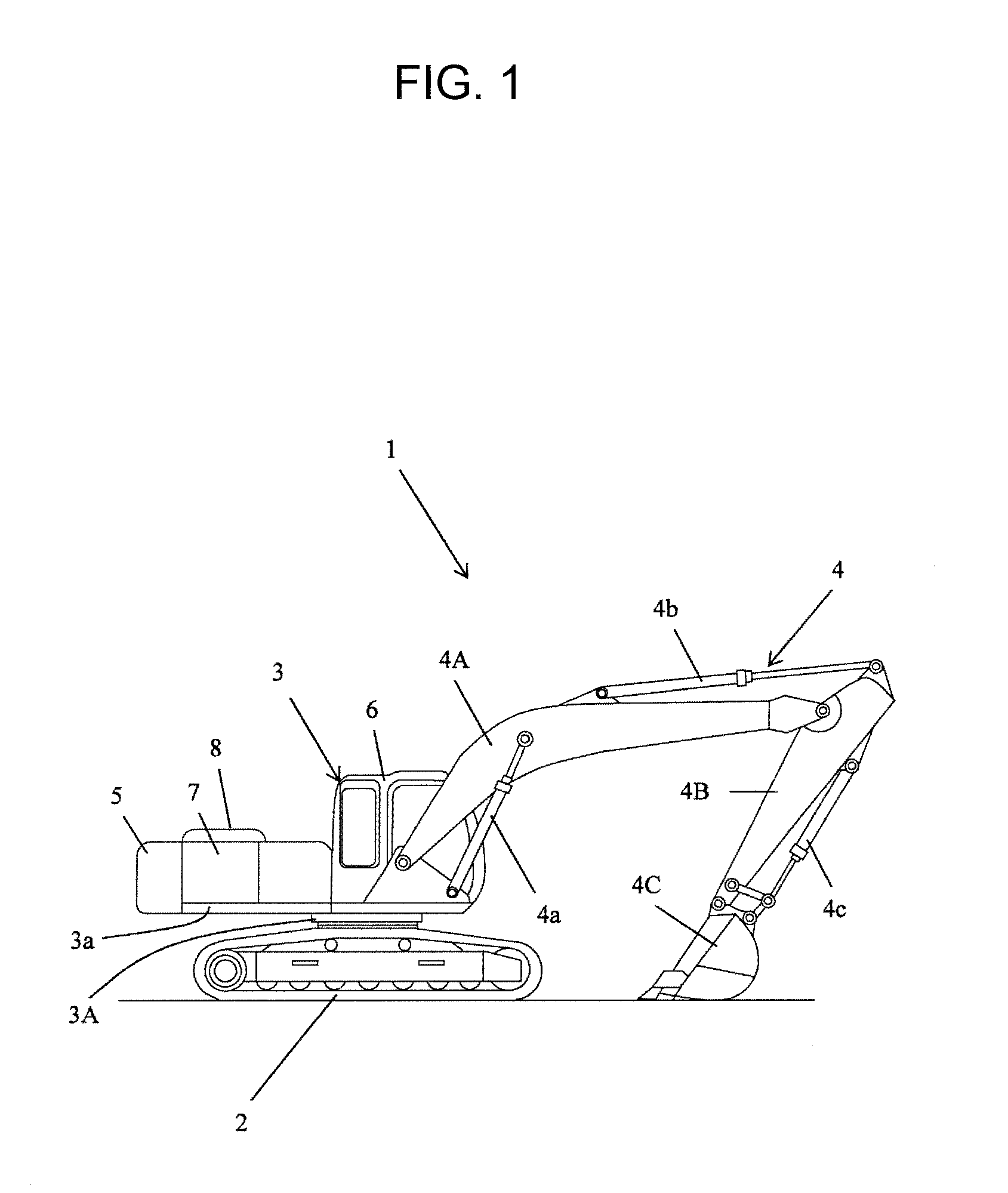
[0041]FIG. 1 is a view illustrating the configurations of a hydraulic excavator taken as an example of a working machine in which a first embodiment of the hydraulic rotating equipment according to the present invention can be arranged.

[0042]The first embodiment of the hydraulic rotating equipment according to the present invention can be arranged in a working machine, for example, a crawler hydraulic excavator 1 that is shown in FIG. 1 and performs work such as digging. This hydraulic excavator 1 is constructed of a travel base 2, a revolving upperstructure 3 arranged on an upper side of the travel base 2 and having a revolving frame 3a, a swing mechanism 3A interposed between these travel base 2 and revolving upperstructure 3 for swinging the revolving upperstructure 3, and a front working mechanism 4 attached to a front part of the revolving upperstructure 3 such that the front working mechanism is pivotal in an up-to-down direction.

[0043]The front working mechanism 4 includes a ...

second embodiment

[0064]FIG. 7 is a view depicting on an enlarged scale a state of sliding contact in a vicinity B in FIG. 5 when the rotational speed of the cylinder block in the hydraulic rotating equipment of the related art has increased from the low speed, and FIG. 8 is a view illustrating the configurations of essential parts of a second embodiment of the present invention, and is a front view of a valve plate as viewed from a cylinder block.

[0065]As depicted in FIG. 7, when the rotational speed of the cylinder block 14 increases from a low speed, the dynamic pressure of an oil film between the valve plate 16 and the cylinder block 14 rises and a wedge film tends to be formed between the valve plate 16 and the cylinder block 14. In an oil film formed between the seal land 16C of the valve plate 16 on the side of the high-pressure port 16B and the cylinder block 14, the oil film in a downstream vicinity B relative to the direction of rotation (forward direction) 25A of the cylinder block 14 beco...

third embodiment

[0068]FIG. 9 is a view illustrating the configurations of essential parts of a third embodiment of the present invention, and is a front view of a valve plate as viewed from a cylinder block.

[0069]The third embodiment of the present invention is different from the above-mentioned second embodiment in that as illustrated, for example, in FIG. 9, a sliding contact member in the third embodiment is comprised of three pads 30A-30C arranged at intervals along the circumferential direction of the rotating shaft 13 and groove portions 31 are formed as flow passages for hydraulic oil between these individual pads 30A-30C, while as illustrated in FIG. 8, the sliding contact member in the second embodiment is comprised of the pad 30 arranged deviating to the downstream side relative to the direction of rotation (forward direction) 25A of the rotating shaft 13 in the above-mentioned range 26B of the predetermined angle 26A along the circumferential direction of the rotating member 13. It is to...


PUM


Abstract

Disclosed is hydraulic rotating equipment provided with a rotating shaft, a cylinder block including a plurality of cylinders, a like plurality of pistons accommodated in the cylinders, respectively, and a valve plate maintained in slide contact with a rear end surface of the cylinder block. The valve plate includes a low-pressure port communicable with the cylinders, a high-pressure port formed in an arcuate shape over a predetermined angle along a circumferential direction of the rotating shaft and communicable with the cylinders, a seal land maintained in slide contact with the rear end surface, and a sliding contact member arranged on a periphery of the seal land in a range of the predetermined angle along the circumferential direction of the rotating shaft and maintained in slide contact with the rear end surface. A working machine provided with the hydraulic rotating equipment is also disclosed.

Description

CROSS-REFERENCE TO RELATED APPLICATION[0001]This application claims the priority of Japanese Patent Application 2013-259315 filed Dec. 16, 2013, which is incorporated herein by reference.BACKGROUND OF THE INVENTION[0002]1. Field of the Invention[0003]This invention relates to hydraulic rotating equipment suited for use as a hydraulic pump, hydraulic motor or the like, and also to a working machine provided with the hydraulic rotating equipment.[0004]2. Description of the Related Art[0005]In general, hydraulic rotating equipment which are widely used as hydraulic pumps, hydraulic motors and the like are each provided, for example, with a cylindrical casing forming an outer shell, a rotating shaft connected to an output shaft of a prime mover and rotatably arranged in the casing, a cylinder block defining therein a plurality of cylinders formed at intervals in a circumferential direction of the rotating shaft, and a like plurality of pistons accommodated in the plurality of cylinders,...

Claims


Application Information

Patent Timeline
IPC IPC(8): F04B1/20F03C1/06
CPCF04B1/2078F03C1/0668F03C1/0639F04B1/2092F04B1/2035F04B1/2042F04B1/303
Inventor SUZUKI, KENTASUZUKI, MOTOSHISAKURAI, SHIGEYUKIHEMMI, MAKOTO
Owner HITACHI CONSTR MASCH CO LTD
Learn More