
Diagnostic system and diagnostic method for internal combustion engine

a diagnostic system and internal combustion engine technology, applied in the direction of machines/engines, electric control, instruments, etc., can solve the problems of increased ratio of the injection amount abnormal diagnosis of the air-fuel ratio of the port injector, etc., to achieve accurate abnormal diagnosis of the in-cylinder injector, high accuracy, and high accuracy

Active Publication Date: 2015-06-18
TOYOTA JIDOSHA KK
View PDF4 Cites 14 Cited by
  • Summary
  • Abstract
  • Description
  • Claims
  • Application Information

AI Technical Summary

Benefits of technology

The patent text describes a configuration that allows for accurate diagnosis of abnormalities in the air-fuel ratio of in-cylinder injectors and port injectors. This is achieved by performing abnormality diagnosis of the in-cylinder injectors in the situation where fuel is only injected from these injectors, and then subsequently making a diagnosis of the port injectors. This ensures high accuracy in identifying the root causes of the abnormalities. Additionally, the patent is also able to presume an abnormality in the intake system when both in-cylinder injectors and port injectors are abnormal simultaneously, which further helps in identifying the cause of the abnormality.

Problems solved by technology

Furthermore, irrespective of whether there is an abnormality of the air-fuel ratio due to the in-cylinder injectors, after an abnormality diagnosis of the air-fuel ratio due to the in-cylinder injectors has been made, an abnormality diagnosis of the air-fuel ratio due to the port injectors is made.
The port injectors are subjected to abnormality diagnosis in not only the operating situation in which fuel is injected from both the in-cylinder injectors and the port injectors but also the operating situation in which the ratio of the injection amount of the port injectors is increased.

Method used


Image

  • Diagnostic system and diagnostic method for internal combustion engine
  • Diagnostic system and diagnostic method for internal combustion engine
  • Diagnostic system and diagnostic method for internal combustion engine

Examples


Embodiment Construction

[0030]Hereinafter, embodiments of the invention will be described with reference to the accompanying drawings. In the following description, like reference numerals denote the like components. The names and functions of them are the same. Thus, the detailed description thereof is not repeated.

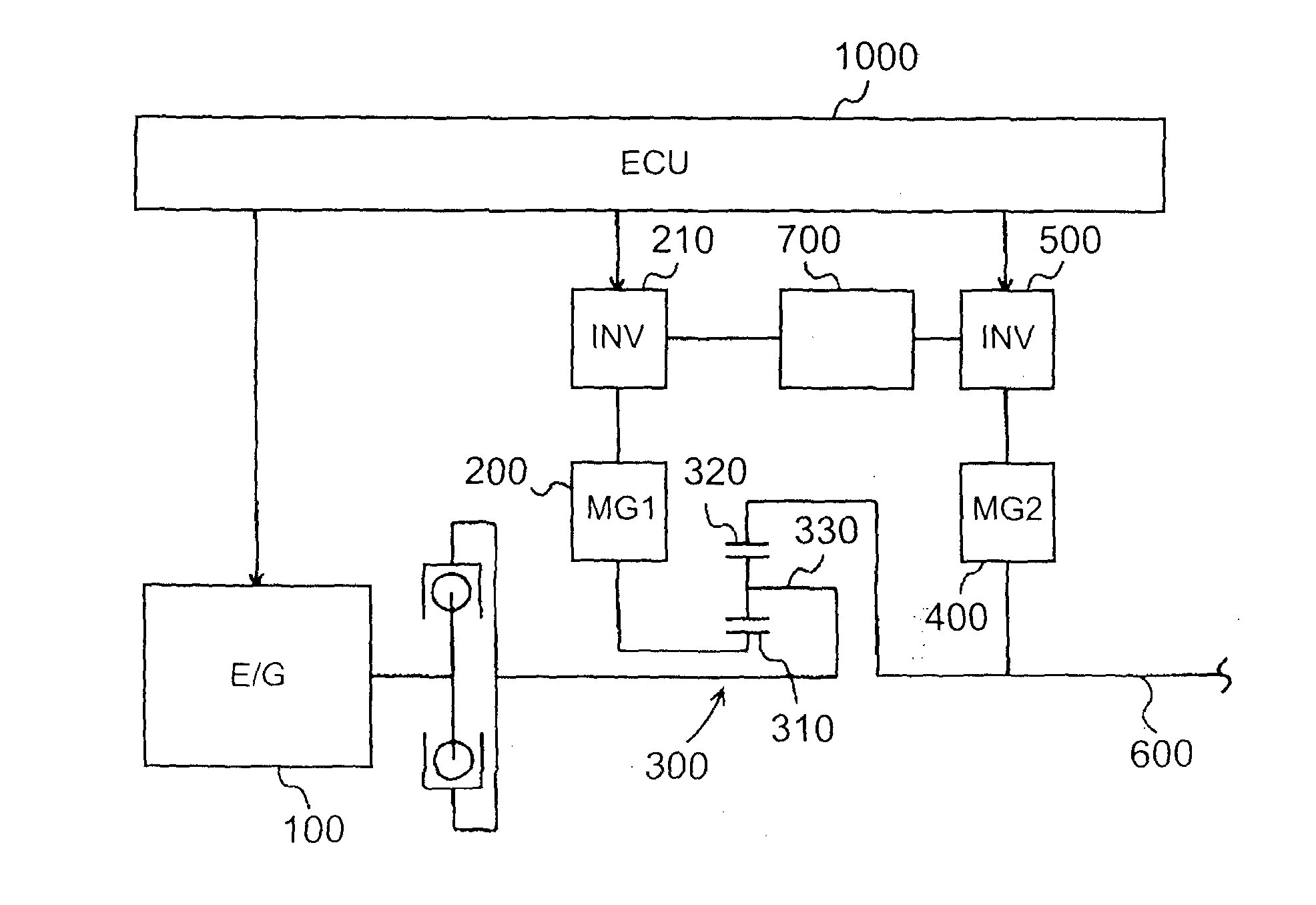
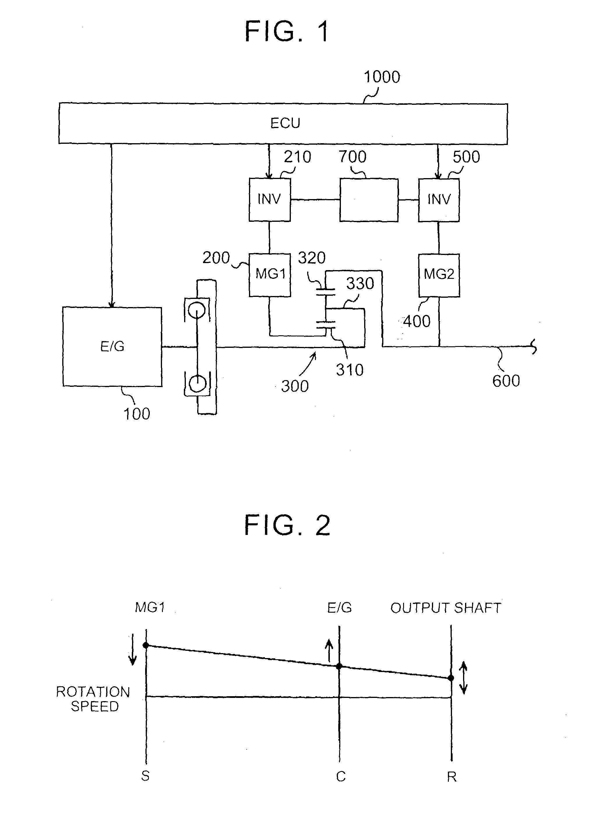
[0031]A power train of a hybrid vehicle on which a diagnostic system according to a first embodiment is mounted will be described with reference to FIG. 1. The diagnostic system according to the present embodiment is, for example, implemented by an electronic control unit (ECU) 1000.

[0032]As shown in FIG. 1, the power train is mainly formed of an engine 100, a first motor generator (MG1) 200, a power split mechanism 300 and a second motor generator (MG2) 400. The power split mechanism 300 combines or distributes torque between these engine 100 and first motor generator 200.

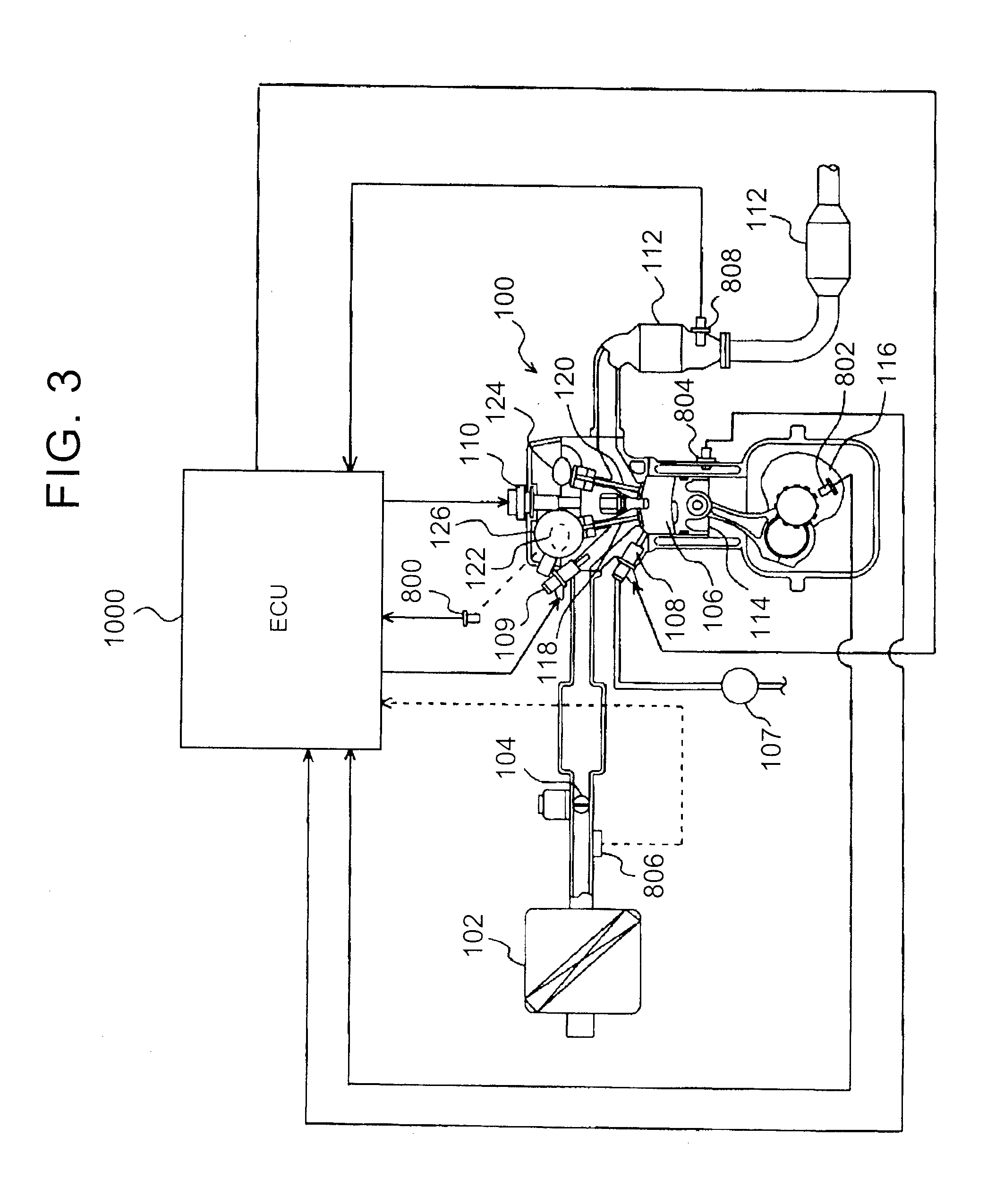
[0033]The engine 100 is a power unit that outputs power by burning fuel, and is configured to be able to electrically contr...


PUM


Abstract

A diagnostic system for an engine includes: a plurality of cylinders, in-cylinder injectors, port injectors and an electronic control unit. The electronic control unit configured to make an abnormality diagnosis of an air-fuel ratio due to the in-cylinder injectors and then to make an abnormality diagnosis of the air-fuel ratio due to the port injectors. The electronic control unit is configured to make an abnormality diagnosis of the air-fuel ratio due to the in-cylinder injectors in an operating situation in which fuel is injected from only the in-cylinder injectors, and to make an abnormality diagnosis of the air-fuel ratio due to the port injectors by increasing a ratio of an injection amount of the port injectors when the electronic control unit has diagnosed that there is an abnormality of the air-fuel ratio in an operating situation in which fuel is injected from both the in-cylinder injectors and the port injectors.

Description

BACKGROUND OF THE INVENTION[0001]1. Field of the Invention[0002]The invention relates to a diagnostic system and diagnostic method for an internal combustion engine. Specifically, the invention relates to a technique for carrying out a diagnosis of a difference in air-fuel ratio among a plurality of cylinders in an internal combustion engine in which an injector that injects fuel inside a corresponding one of cylinders and an injector that injects fuel outside a corresponding one of the cylinders are provided in correspondence with each of the cylinders.[0003]2. Description of Related Art[0004]There is known an internal combustion engine in which an injector that injects fuel is provided in correspondence with each of a plurality of cylinders. In such an internal combustion engine, for example, if the injection amount of the injector becomes insufficient in only part of the cylinders, the air-fuel ratio of each of the part of the cylinders may deviate from the air-fuel ratio of the ...

Claims


Application Information

Patent Timeline
Patent Type & Authority Applications(United States)
IPC IPC(8): F02D41/26
CPCF02D41/26F02D41/1495F02D41/221F02D41/3094F02D2041/224F02D2200/1015
Inventor MATSUMOTO, TAKASHI
Owner TOYOTA JIDOSHA KK
Learn More