
Heating platform and 3D printing apparatus

a technology of printing apparatus and heating platform, which is applied in the direction of additive manufacturing process, application, manufacturing tools, etc., can solve the problems of easy temperature unevenness on the surface of the substrate, object burnt, etc., and achieve good heating effect

Inactive Publication Date: 2015-06-18
XYZPRINTING +2
View PDF12 Cites 23 Cited by
  • Summary
  • Abstract
  • Description
  • Claims
  • Application Information

AI Technical Summary

Benefits of technology

The invention provides a heating platform and a 3D printing apparatus with good heating and printing effects. The heating plate directly heats the substrate and a conducting plate with less area is attached to it. The conducting plate transfers the heat from the heating plate to the substrate, and a temperature sensing element adjusts the substrate temperature to prevent burnt objects. The conducting plate is heated easier and can transfer its thermal energy to the outside, reducing temperature differences between different regions of the substrate. The heating platform and the 3D printing apparatus have good heating and printing effects.

Problems solved by technology

Nevertheless, when the substrate is manufactured as having a larger area, temperature unevenness occurs easily on surfaces of the substrate, for example, the central portion of the substrate has a higher temperature, while the peripheral portion of the substrate has a lower temperature.
Therefore, if the temperature sensing element adjusts the temperature of the substrate only according to the temperature in part of the substrate, the central portion of the substrate may be probably overheated, which cause the 3D object to be burnt, or the peripheral portion of the substrate may probably be excessively cold, which causes the 3D object to be unexpectedly cured.

Method used


Image

  • Heating platform and 3D printing apparatus
  • Heating platform and 3D printing apparatus
  • Heating platform and 3D printing apparatus

Examples


Embodiment Construction

[0024]It is to be understood that the foregoing and other detailed descriptions, features, and effects are intended to be described more comprehensively by providing embodiments accompanied with figures hereinafter. In the following embodiments, wording used to indicate directions, such as “up,”“down,”“front,”“back,”“left,” and “right,” merely refers to directions in the accompanying drawings. Therefore, the directional wording is used to illustrate rather than limit the invention. Moreover, the same or similar reference numerals represent the same or similar elements in the following embodiments.

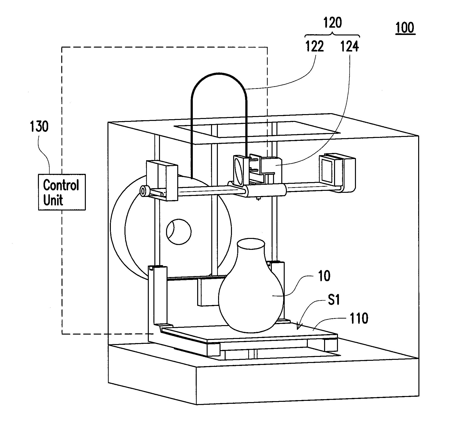
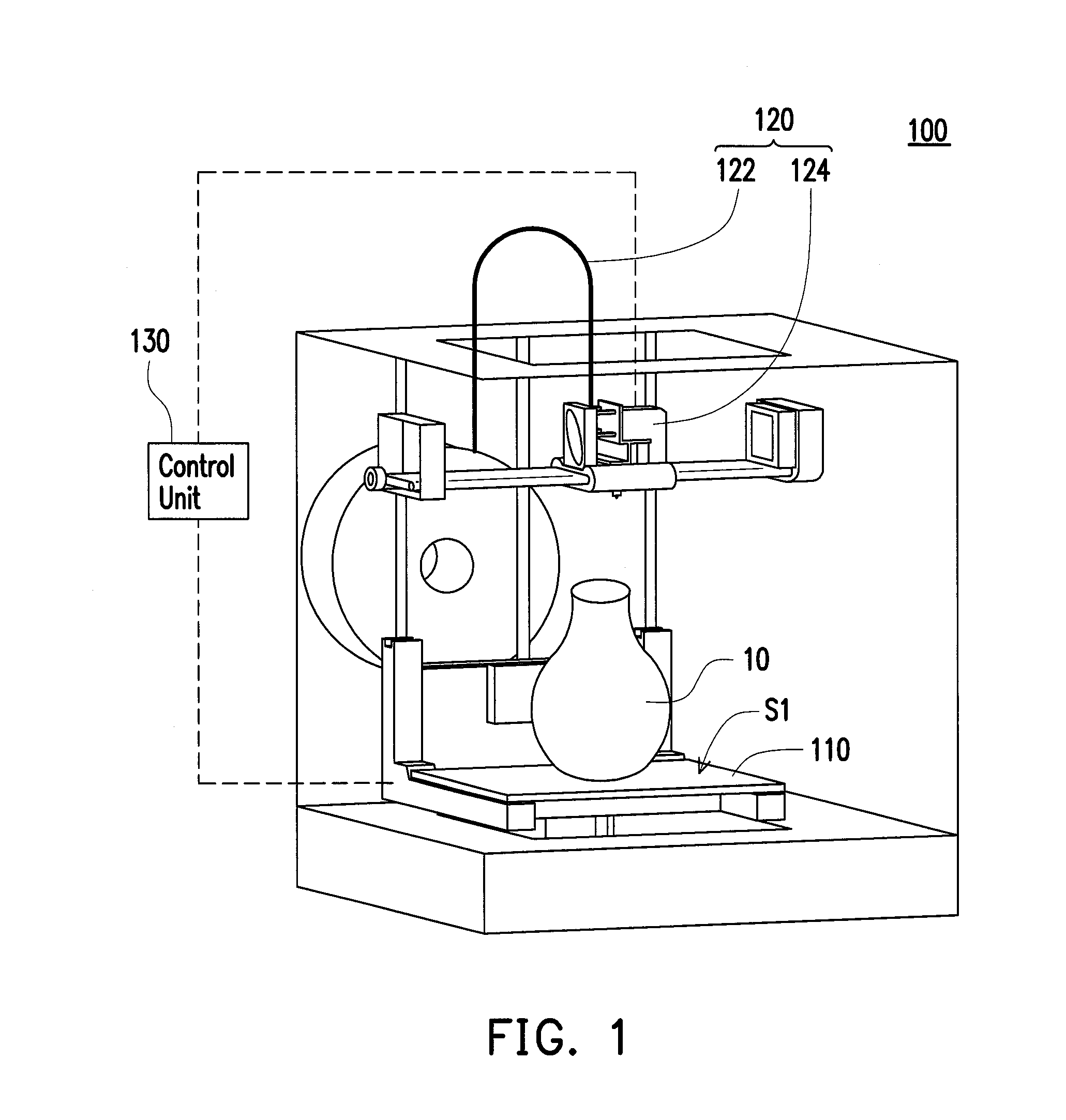
[0025]FIG. 1 is a schematic diagram of a three dimensional (3D) printing apparatus according to an embodiment of the invention. With reference to FIG. 1, in the present embodiment, a 3D printing apparatus 100 includes a heating platform 110, a printing unit 120 and a control unit 130. The printing unit 120 is movably disposed above the heating platform 110. The control unit 130 is electrica...


PUM

PropertyMeasurementUnit
Temperatureaaaaaaaaaa
Thicknessaaaaaaaaaa
Electrical conductoraaaaaaaaaa

Abstract

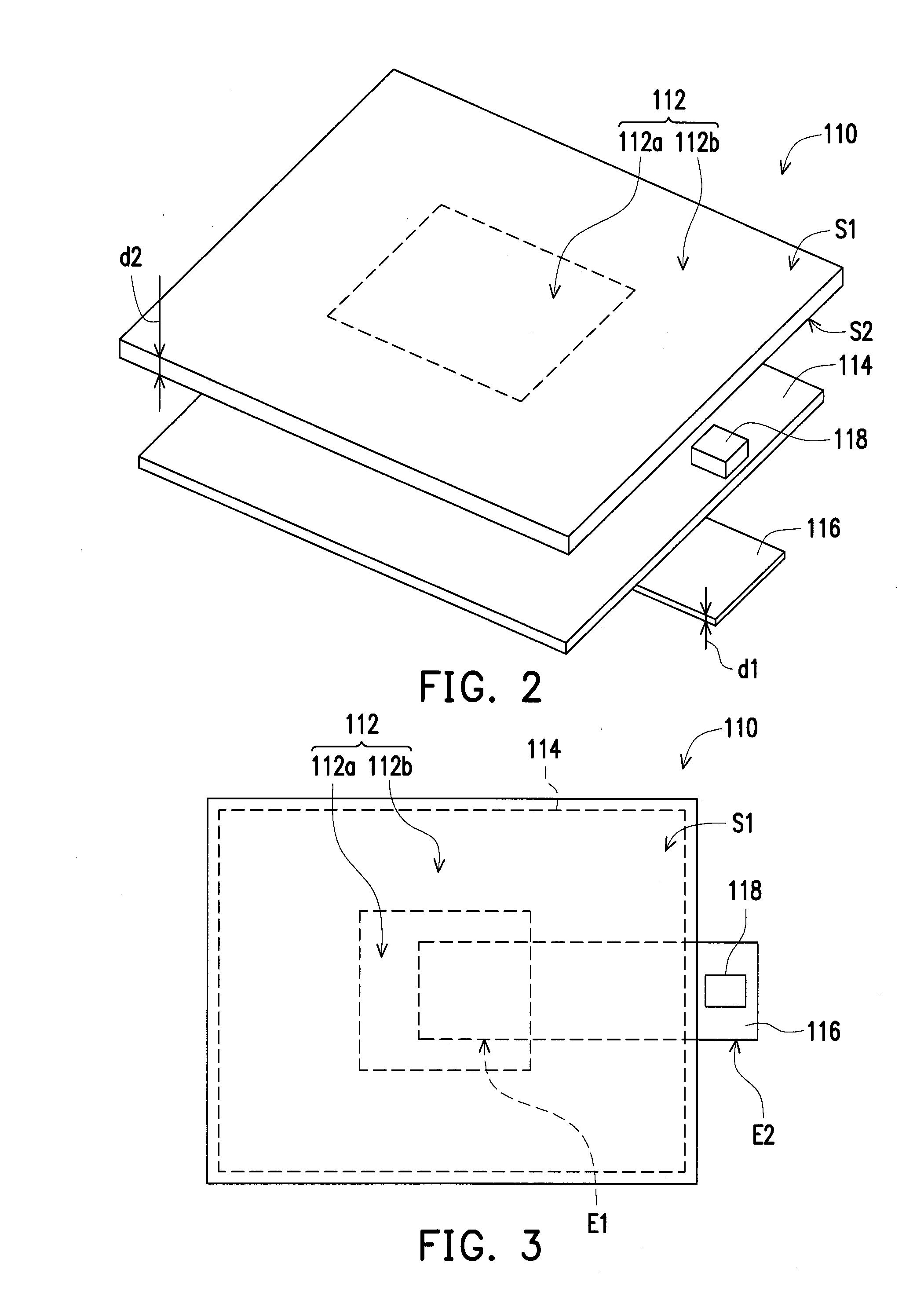
A heating platform including a substrate, a heating plate, a conducting plate and a temperature sensing element is provided. The substrate has a first surface for forming a three dimensional (3D) object and an opposite second surface. The heating plate is attached to the second surface of the substrate to heat the substrate. The conducting plate is attached to the heating plate, and the heating plate is coved between the substrate and the conducting plate, wherein the area of the conducting plate is smaller than the area of the substrate, and an end of the conducting plate extends to the outer of the heating plate. The temperature sensing element is disposed at the end of the conducting plate extending to the outer of the heating plate to sense the temperature of the substrate through the conducting plate. A 3D printing apparatus including the heating platform aforementioned is also provided.

Description

CROSS-REFERENCE TO RELATED APPLICATION[0001]This application claims the priority benefit of Taiwan application serial no. 102223491, filed on Dec. 12, 2013. The entirety of the above-mentioned patent application is hereby incorporated by reference herein and made a part of this specification.BACKGROUND[0002]1. Field of the Invention[0003]The invention is directed to a heating platform and a printing apparatus and more particularly, to a heating platform and a 3D printing apparatus applying the heating platform.[0004]2. Description of Related Art[0005]Along with the progress in computer-aided manufacturing (CAM), manufacturers have developed the three-dimensional (3D) printing technology to rapidly fabricate an original design concept. The 3D printing technology is by meaning a collective term referring to a series of rapid prototyping (RP) techniques, and the basic principle is additive manufacturing, where a RP machine is used to form cross-sectional shapes of a workpiece in an X-Y...

Claims


Application Information

Patent Timeline
IPC IPC(8): B29C67/00H05B3/22
CPCB29C67/0088B29C67/0092H05B3/22B29C64/106B29C64/118B29C64/393B29C64/40H05B1/023
Inventor HO, KWANCHANG, CHIH-MING
Owner XYZPRINTING
Learn More