Apparatus and method for controlling transmission power of terminal in wireless environment
a technology of wireless network and terminal, applied in the direction of power management, wireless communication, eavesdropping prevention circuit, etc., can solve the problems of increased power consumption, power control scheme, and difficulty for terminals or access point controllers to accurately measure the radio wave environment for transmission power control in real tim
- Summary
- Abstract
- Description
- Claims
- Application Information
AI Technical Summary
Benefits of technology
Problems solved by technology
Method used
Image

Examples
embodiment 1
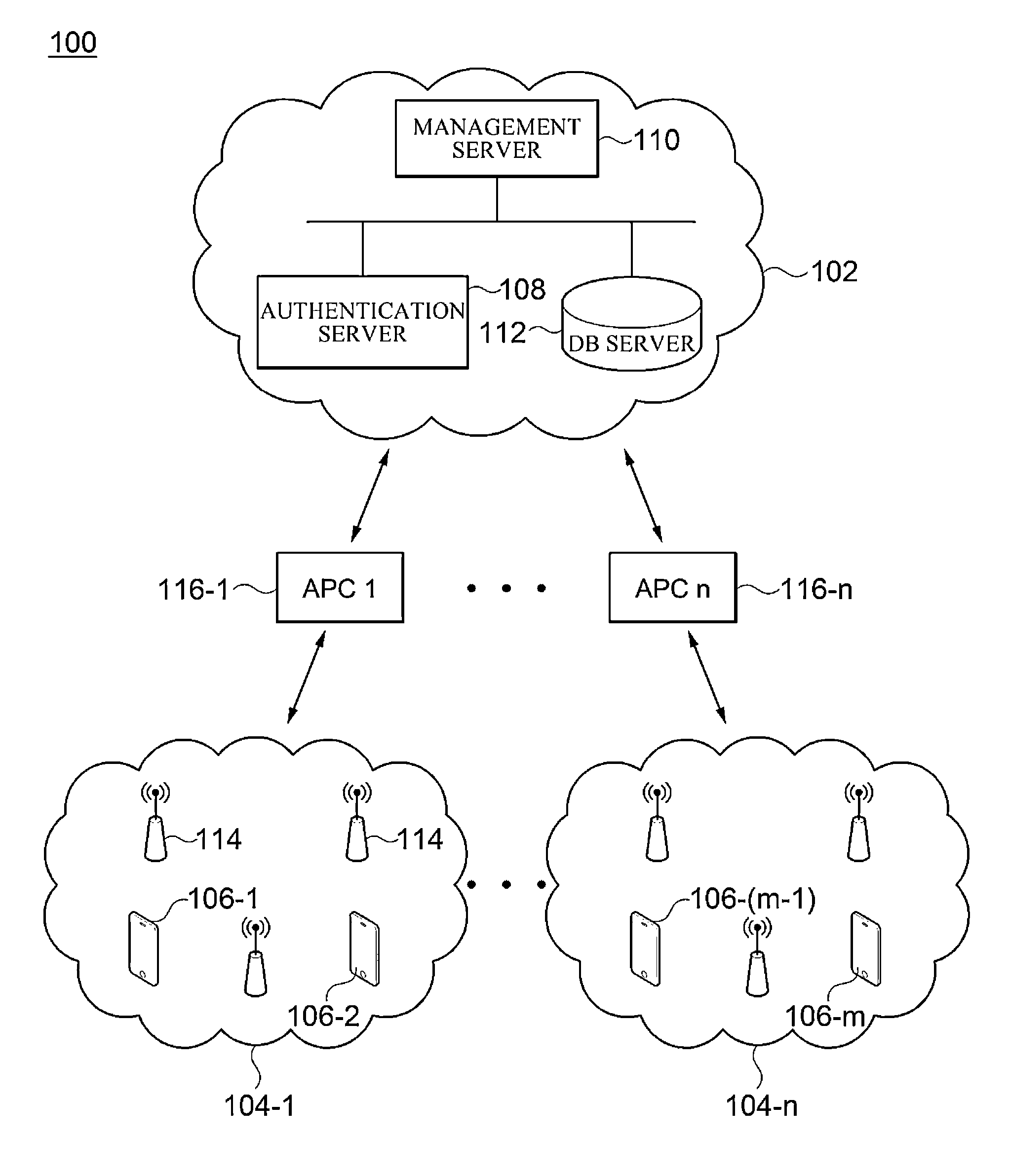
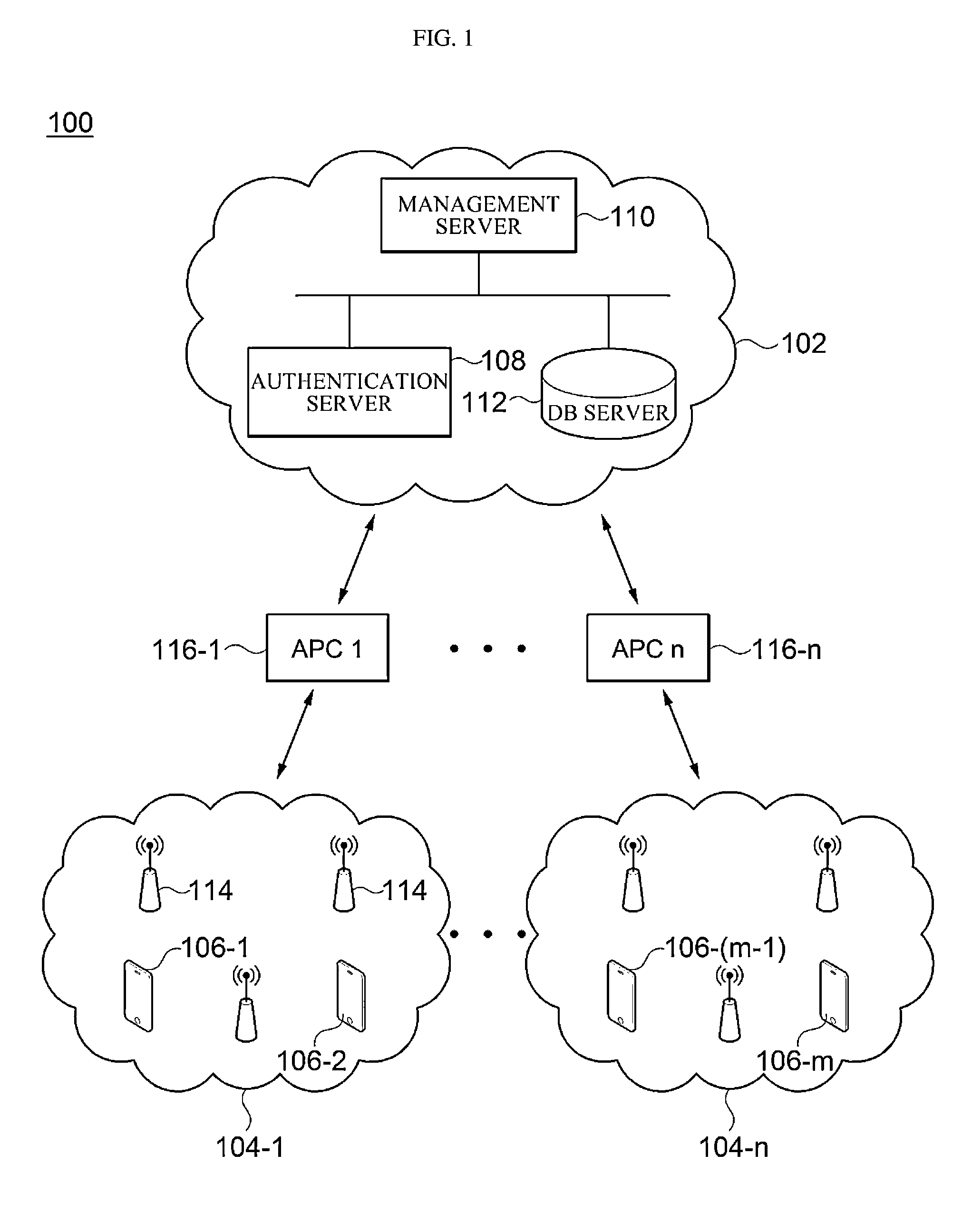
[0124]When the terminal i(106-i) approaches the wireless network k(104-k), a wireless communication unit 710 of the terminal i(106-i) recognizes the wireless network k(104-k) from a broadcasting packet or the like that is received from the wireless network k(104-k). Then, the authentication control unit 716 transmits an authentication request to an authentication server 108 of a back-end server group 102 using user authentication information and terminal information that are set by a user.
[0125]The authentication server 108 performs user authentication according to the authentication request and acquires the optimal transmission power value of the terminal i(106-i) with respect to the wireless network k(104-k) from the management server 110 when the authentication succeeds. Specifically, the authentication server 108 provides information on the wireless network k(104-k) accessed by the terminal i(106-i), information e on an accessed frequency band, and identification information (a ...
embodiment 2
[0128]When the terminal i(106-i) recedes from the wireless network to which the terminal is connected, a transmission power control unit 718 of the wireless network access agent 714 senses the disconnection from the wireless network k(104-k) and operates a timer time_recovery. If the terminal i(106-i) does not access the wireless network k(104-k) by the time the timer expires, the transmission power control unit 718 considers the terminal i(106-i) to have completely receded from the wireless network k(104-k) and reads a default transmission power value MT_i_DFT_TP from the file system 712 to deliver the default transmission power value MT_i_DFT_TP to the wireless communication unit 710. In this case, a setting time of the timer may be set appropriately according to characteristics of a terminal and a network and operating policies.
[0129]The wireless communication unit 710 sets the default transmission power value received through the transmission power control unit 718 to allow data...
embodiment 3
[0130]When the terminal i(106-i) enters the wireless network 1(104-1), the terminal i(106-i) performs authentication using the same method as in embodiment 1.
[0131]FIGS. 8 and 9 are views for describing an effect according to embodiments of the present disclosure. First, FIG. 8 is a graph for comparing a transmission power consumption amount according a distance from the access point 114 to a terminal to which the transmission power control method according to embodiments of the present disclosure has been applied and a terminal to which the method has not been applied.
[0132]Change in transmission power according to a distance of the terminal to which the method has not been applied is shown as a dotted line in FIG. 8. This may be expressed as the following equation: y=MT_i_DFT_TP (where MT_i_DEF_TP is a default power value of the terminal).
[0133]Next, change in transmission power according to a distance of the terminal to which the transmission power control method according to emb...
PUM
 Abstract
Description
Claims
Application Information
 - R&D
- Intellectual Property
- Life Sciences
- Materials
- Tech Scout
- Unparalleled Data Quality
- Higher Quality Content
- 60% Fewer Hallucinations
Browse by: Latest US Patents, China's latest patents, Technical Efficacy Thesaurus, Application Domain, Technology Topic, Popular Technical Reports.
© 2025 PatSnap. All rights reserved.Legal|Privacy policy|Modern Slavery Act Transparency Statement|Sitemap|About US| Contact US: help@patsnap.com