Shift Arrangement For A Motor Vehicle Transmission and Method for Actuating Said Shift Arrangement

a technology for motor vehicles and shift arrangements, which is applied in the direction of gearing control, gearing elements, gearing, etc., can solve the problems of large diameter of individual shift drums, large space occupation of shift arrangements, and sequential shift sequences that are difficult to achieve, and achieve low packaging requirements , the effect of short shifting times

Inactive Publication Date: 2015-06-04
GETRAG GETRIEBE & ZAHNRADFABRIK HERMANN HAGENMEYER GMBH & CO KG
View PDF4 Cites 4 Cited by
  • Summary
  • Abstract
  • Description
  • Claims
  • Application Information

AI Technical Summary

Benefits of technology

This patent is about a shift arrangement for transmitting power in automobiles. The arrangement allows for the use of a single electric motor to engage and disengage the gears. It also allows for quick shifting and free shift sequences. The arrangement is compact, cost-effective, and can be used in dual clutch transmissions. The technical effects of this patent are improved efficiency and a more flexible and compact shift arrangement.

Problems solved by technology

In the latter case, disadvantages in terms of shifting time arise from the sequential shift sequence.
Moreover, the resulting diameter of the individual shift drum is very large, and therefore the shift arrangement occupies a relatively large space within the transmission housing.

Method used


Image

  • Shift Arrangement For A Motor Vehicle Transmission and Method for Actuating Said Shift Arrangement
  • Shift Arrangement For A Motor Vehicle Transmission and Method for Actuating Said Shift Arrangement
  • Shift Arrangement For A Motor Vehicle Transmission and Method for Actuating Said Shift Arrangement

Examples


Embodiment Construction

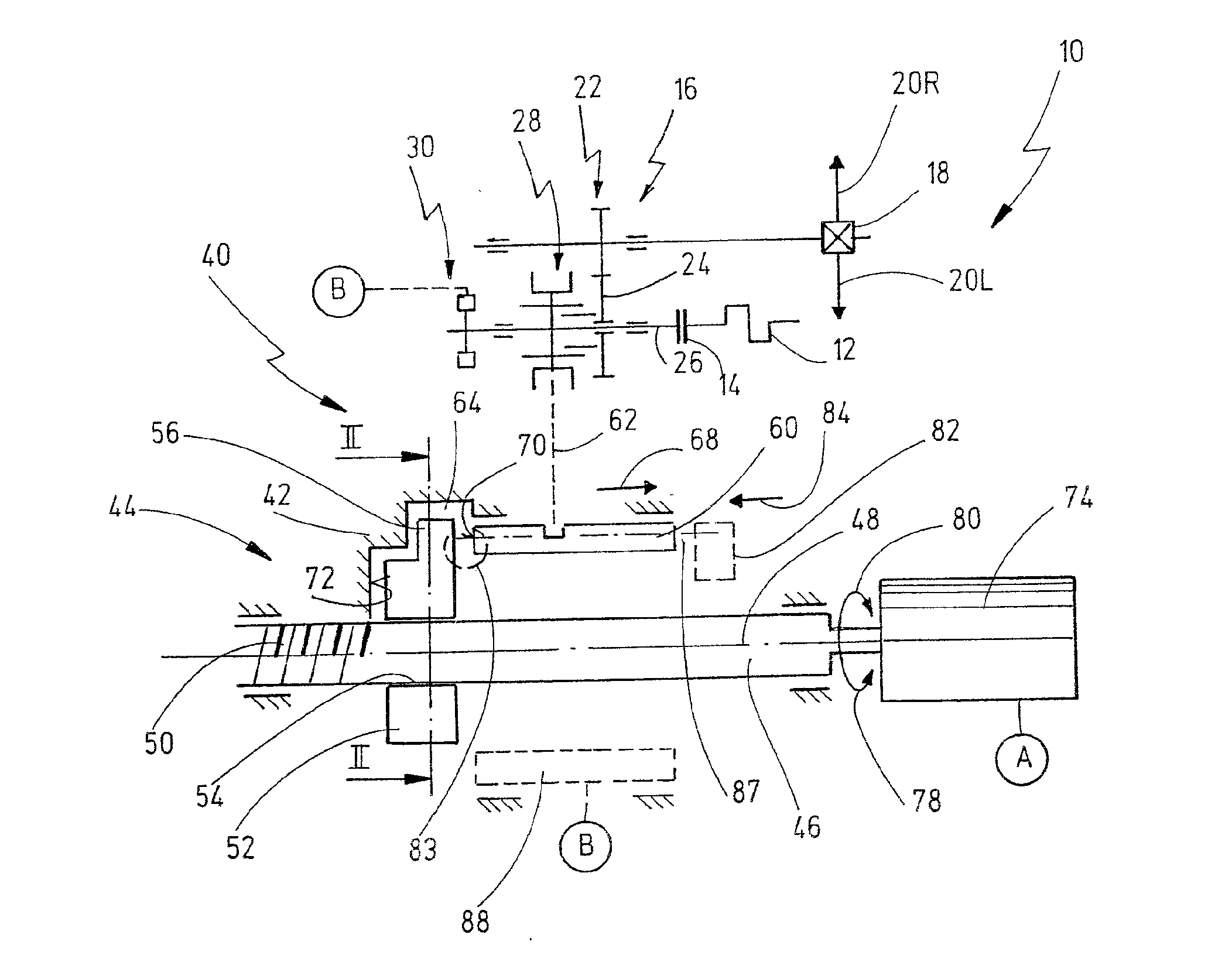
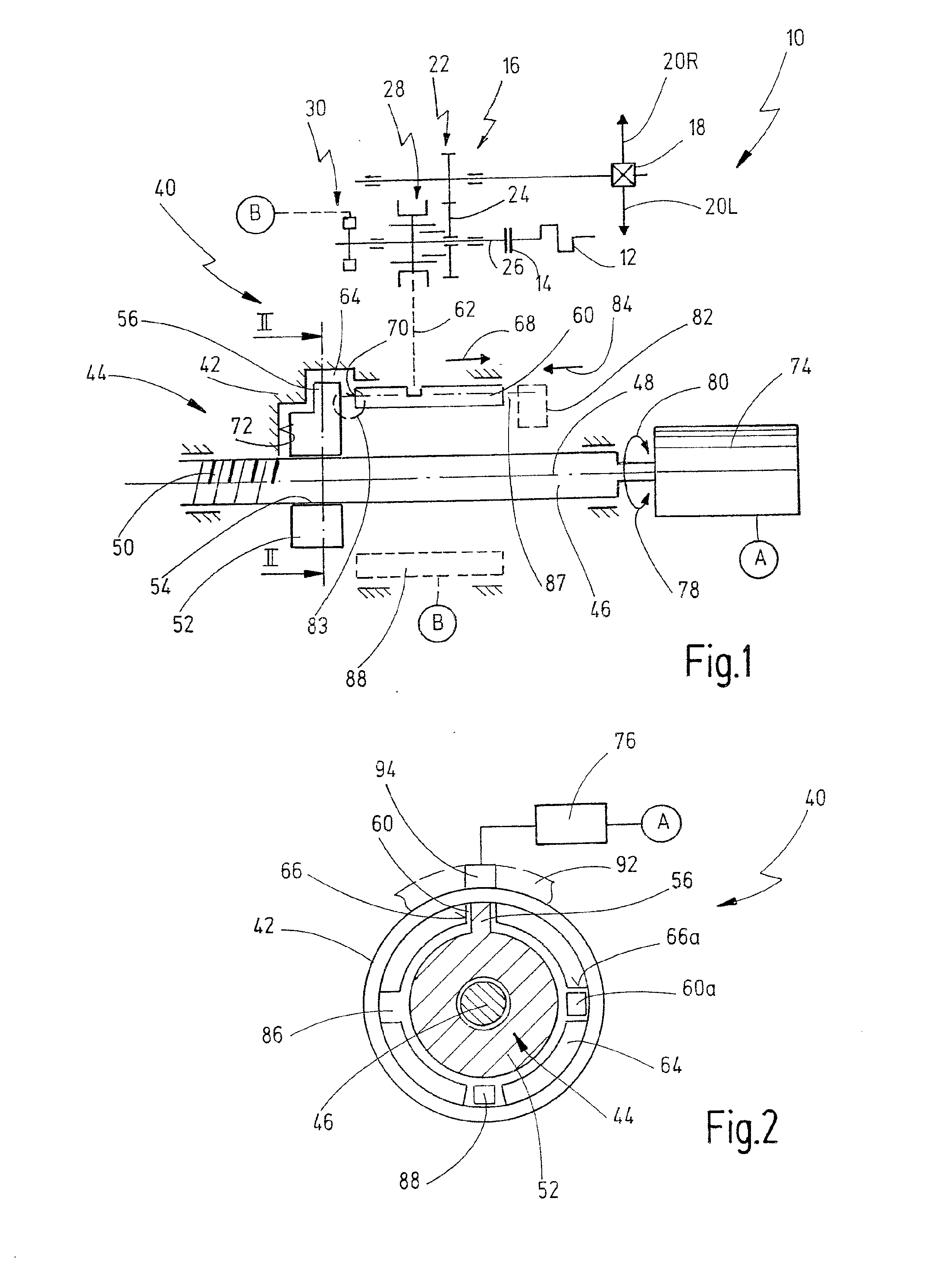
[0088]In FIGS. 1 and 2, a drive train for a motor vehicle is illustrated schematically and denoted overall by 10. The drive train 10 contains a drive motor 12, e.g. an internal combustion engine, the drive shaft of which is connected to a clutch arrangement 14. An output of the clutch arrangement 14 is connected to a transmission arrangement 16. An output of the transmission arrangement 16 is connected to a differential 18, by means of which motive power is distributed between two driven wheels 20L, 20R. In the present case, the transmission arrangement 16 is indicated only in a schematic way by means of an input shaft and an output shaft, which are connected to one another by a gear set 22. The transmission arrangement 16 is, in particular, a spur gear transmission, in particular a layshaft transmission. In particular, the transmission arrangement 16 can be an automated shift transmission, preferably a dual clutch transmission.

[0089]The gear set 22 has a loose gear 24, which is mou...


PUM


Abstract

Shift arrangement for a motor vehicle transmission which has at least two gear stages that can be engaged and disengaged by means of different rods has a housing. At least two push rods are mounted on the housing in such a way as to be movable in an axial direction between a neutral position and at least one shift position and which can each be coupled to a shift clutch or a shift clutch pack. At least two return rods are mounted on the housing in such a way as to be movable in an axial direction between a neutral position and at least one shift position. The return rods are each coupled to one of the push rods in such a way that a push rod and the return rod associated therewith are moved in opposite axial directions. A shift member is mounted on the housing in such a way that a shift cam of the shift member can be aligned with a push rod or with a return rod for the purpose of selecting, and can transmit a pushing force to the selected rod and move it in a first axial direction for a shift operation. At least one driving feature is arranged on the shift member in such a way that, before or during a shift operation on a selected rod, the driving feature can transmit a pushing force to at least one unselected rod in order to move said unselected rod into the neutral position.

Description

CROSS REFERENCES TO RELATED APPLICATIONS[0001]This application claims the priority of German patent application DE 10 2013 018 103.8 filed Dec. 3, 2013.BACKGROUND OF THE INVENTION[0002]The present invention relates to a shift arrangement for a motor vehicle transmission which has at least two gear stages, which can be engaged and disengaged by means of different rods.[0003]The present invention furthermore relates to a method for actuating a shift arrangement of a motor vehicle transmission which has at least two gear stages.[0004]Shift arrangements of this kind are known in the prior art. In general, a motor vehicle transmission has one shift clutch pack for every two gear stages, said pack consisting of two shift clutches, which can be actuated by means of a common sliding sleeve. In this case, the shift clutches can be claw clutches but are preferably synchronizing shift clutches. The motor vehicle transmission is preferably a spur gear transmission of layshaft construction.[0005...

Claims


Application Information

Patent Timeline
Patent Type & Authority Applications(United States)
IPC IPC(8): F16H21/08F16H37/12
CPCF16H37/12F16H21/08F16H63/304F16H2063/3053F16H2063/3063F16H2063/025Y10T74/19251Y10T74/19279
Inventor BUENDER, CARSTEN
Owner GETRAG GETRIEBE & ZAHNRADFABRIK HERMANN HAGENMEYER GMBH & CO KG
Why Eureka
Try Eureka