Eureka AIR delivers breakthrough ideas for toughest innovation challenges, trusted by R&D personnel around the world.

Dual-clutch transmission

A technology of transmission and clutch, applied in the field of transmission of motor vehicles

Inactive Publication Date: 2016-11-23
SCHAEFFLER TECH AG & CO KG
View PDF6 Cites 1 Cited by
  • Summary
  • Abstract
  • Description
  • Claims
  • Application Information

AI Technical Summary

Problems solved by technology

[0004] The disadvantage of this transmission is that when it switches gear ratios there are time periods during which no gear ratio is engaged and thus no drive torque is applied
It is therefore not possible to change gears without interrupting traction

Method used


Image

  • Dual-clutch transmission
  • Dual-clutch transmission
  • Dual-clutch transmission

Examples


Embodiment Construction

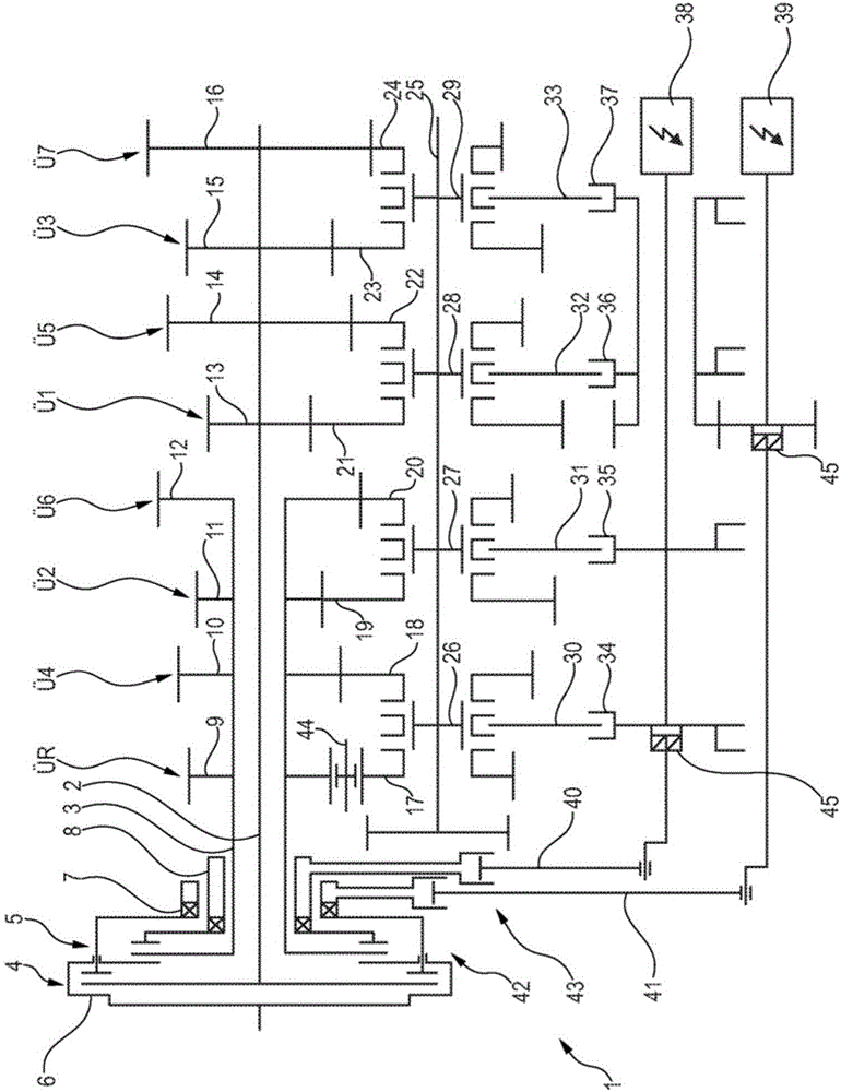
[0026] figure 1 A schematic diagram of a transmission 1 according to the prior art is shown. The transmission 1 has a first input shaft 2 and a second input shaft 3 , which are connectable via clutches 4 , 5 to a crankshaft (not shown) of the engine. The clutches 4, 5 are arranged in a clutch housing 6, which can be connected to the crankshaft, and for actuating the clutches 4, 5 are provided actuating devices 7, 8 which can be controlled by a control unit in order to be able to actuate a clutch 4 and / or another clutch 5. The input shafts 2 , 3 are at least partially arranged coaxially with one another, wherein the actuating devices 7 , 8 are preferably also arranged coaxially with one another. Gears 9, 10, 11, 12, 13, 14, 15, 16 for gear pairs 9 / 17; 10 / 18; 11 / 19; 12 / 20; 13 / 21; 14 / 22; It is non-rotatably connected to the two input shafts 2 , 3 . Here, the gears 9 , 10 , 11 and 12 are connected in a rotationally fixed manner to the shaft 3 , while the gears 13 , 14 , 15 and...


PUM


Abstract

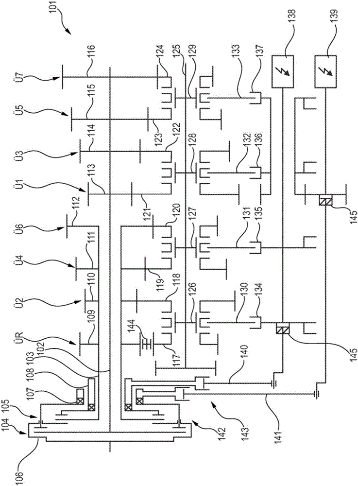
The invention relates to a transmission (1), comprising a first input shaft (102), a second input shaft (103), an output shaft (125), a first clutch (104), and a second clutch (105). Each of the input shafts (102, 103) can be connected to the crankshaft of a drive engine by means of one of the clutches (104, 105) and each of the input shafts (102, 103) can be connected to the output shaft (125) in a torque-transmitting manner by means of gear pairs (113 / 121, 110 / 118, 114 / 122, 111 / 119, 115 / 123, 112 / 120, 116 / 124, 109 / 117). Groups of two gear pairs (113 / 121 and 114 / 122; 115 / 123 and 116 / 124; 111 / 119 and 112 / 120) can be connected to the output shaft (125) in a torque-transmitting manner by means of an actuatable shifting fork (130, 131, 132, 133). A gear ratio (U R, U 1 to U 7) is associated with each gear pair (113 / 121, 110 / 118, 114 / 122, 111 / 119, 115 / 123, 112 / 120, 116 / 124, 109 / 117), wherein a number of gear ratios graded in relation to each other is provided. The two gear ratios of a group of gear pairs are a first gear ratio (N) and the next gear ratio but one (N+2), wherein N is an integer, in particular N = 1, 2, 3, 4, or 5.

Description

technical field [0001] The invention relates to a transmission, in particular for a motor vehicle. Background technique [0002] Various transmissions for motor vehicles are known in the prior art. Thus, so-called manually shifted transmissions are known, in which the transmission input shaft can be connected by a clutch to the crankshaft of the engine, in which an output shaft is also provided, and in which there are multiple gear pairs, one of which can be selected by means of a shift fork. In these gear pairs, in most cases one of the two gears is a fixed wheel, which is fixedly connected to the shaft, and the other gear is a free wheel, which is free to rotate on the shaft, wherein the The gear wheel can also be connected in a rotationally fixed manner to the shaft by means of a locking mechanism. This can also be done by means of a selector fork, which is also referred to as engaging a transmission stage. The clutch is usually engaged or disengaged in a foot-actuate...

Claims


Application Information

Patent Timeline
Patent Type & Authority Applications(China)
IPC IPC(8): F16H3/00
CPCF16H3/006F16H61/18F16H3/089F16H61/32F16H61/688F16H63/18F16H2061/2869F16H2200/0056
Inventor 布鲁诺·米勒拉斯洛·曼彼得·格雷布
Owner SCHAEFFLER TECH AG & CO KG
Why Eureka
Eureka Blog
Learn More