
Method and device for adjusting a threshold value of a fuel flow rate

Active Publication Date: 2015-06-04
SN DETUDE & DE CONSTR DE MOTEURS DAVIATION S N E C M A
View PDF2 Cites 9 Cited by
  • Summary
  • Abstract
  • Description
  • Claims
  • Application Information

AI Technical Summary

Benefits of technology

The patent aims to improve the performance of turbine engines by incorporating a difference in acceleration and deceleration stops to avoid overconstraining or underconstraining the engine during acceleration or deceleration stages. This results in better acceleration and deceleration margins, which ensures that the risk of compressor surging or engine burning out is not overestimated.

Problems solved by technology

By way of example, such malfunctioning may be surging of a compressor of the turbojet during a stage of acceleration or burning out of the turbojet during a stage of deceleration.
Nevertheless, this assumption does not take account of a possible change in the nature of the fuel used relative to the reference fuel, nor does it take account of possible variation in the temperature of the fuel relative to the reference temperature while the turbojet is in operation.
Furthermore, this assumption suffers from various uncertainties associated in particular with the interchangeability of the pieces of electronic equipment used for processing position measurements of the metering device and also associated with the accuracy of those pieces of equipment.
Consequently, using such a relationship leads to inaccuracies in the estimated mass flow rate of fuel injected into the combustion chamber as used while regulating the turbojet.
Unfortunately, if the mass flow rate of fuel being injected into the combustion chamber is underestimated by the fuel metering device, that means that the acceleration margin available to the turbojet during a transient stage of acceleration will on the contrary be overestimated (i.e. the turbojet will be presumed to have an acceleration margin greater than that which would be presumed if the fuel mass flow rate were estimated correctly).
There is thus a risk of undesired acceleration of the turbojet, and potentially of the compressor surging during acceleration.
There is thus a risk of not being able to decelerate correctly.
There thus exists a risk of the turbojet suffering underspeed or burnout.
There thus exists the risk of not being able to accelerate correctly.
The lack of accuracy in the estimate provided by the metering device thus has a non-negligible impact on the regulation of the turbojet and on the performance it achieves.
These acceleration and deceleration stops thus put limits on the performance of the turbine engine.
Furthermore, the estimate delivered by the estimator device, although it is more accurate than the fuel flow rate estimate delivered by the metering device over at least one range of fuel flow rate values, is itself also often vulnerable to failures.

Method used


Image

  • Method and device for adjusting a threshold value of a fuel flow rate
  • Method and device for adjusting a threshold value of a fuel flow rate
  • Method and device for adjusting a threshold value of a fuel flow rate

Examples


Embodiment Construction

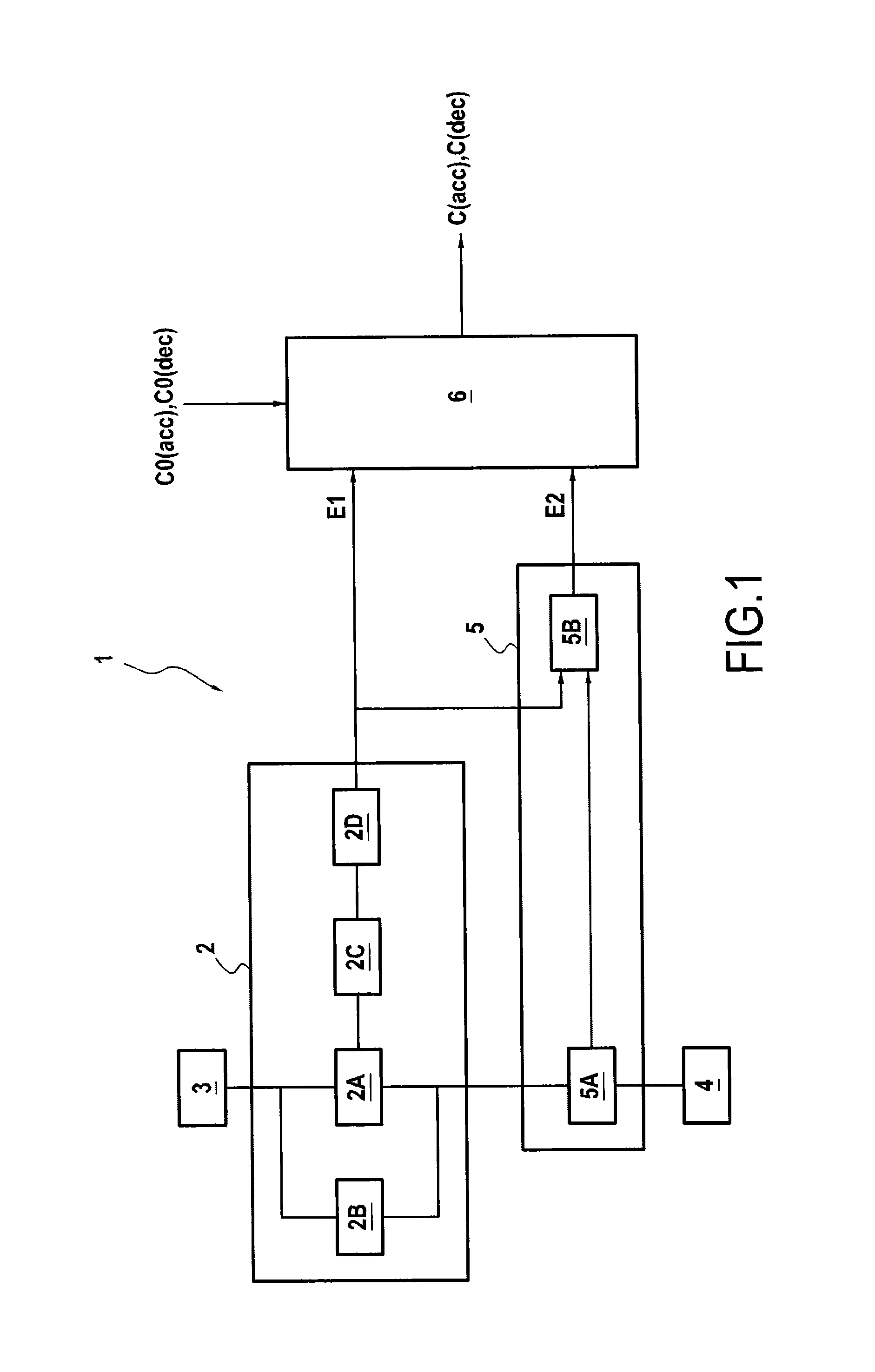
[0081]FIG. 1 is a block diagram of a turbine engine 1 in accordance with the invention, in a particular embodiment.

[0082]In this embodiment, the turbine engine 1 is a turbojet for propelling an airplane. Nevertheless, the invention applies to other turbine engines, such as for example a turboprop, and also to other types of aircraft.

[0083]In accordance with the invention, the turbojet 1 has a fuel metering device 2 suitable for adjusting the quantity of fuel coming from the fuel circuit 3 of the airplane and delivered by the fuel injector system 4 into the combustion chamber of the turbojet.

[0084]As mentioned above, the fuel metering device 2 has a slide 2A (or fuel metering valve FMV) of position that varies as a function of the rate at which fuel is to be injected into the combustion chamber.

[0085]By moving, the slide obstructs a fuel flow section, referenced S, also referred to as the flow area of the metering device. It should be observed that the relationship between the area S...


PUM


Abstract

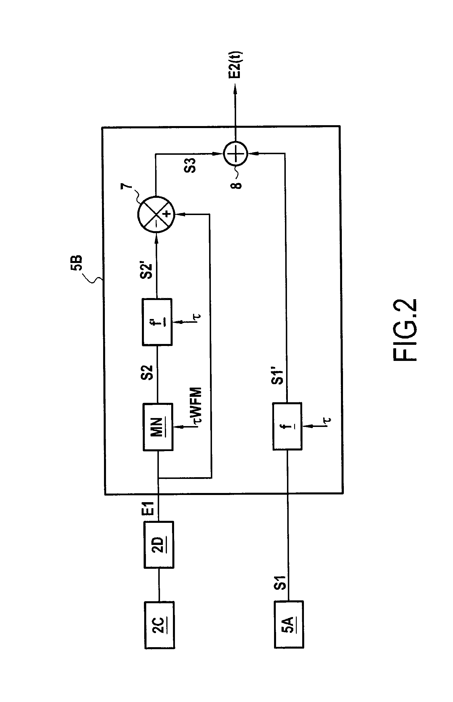
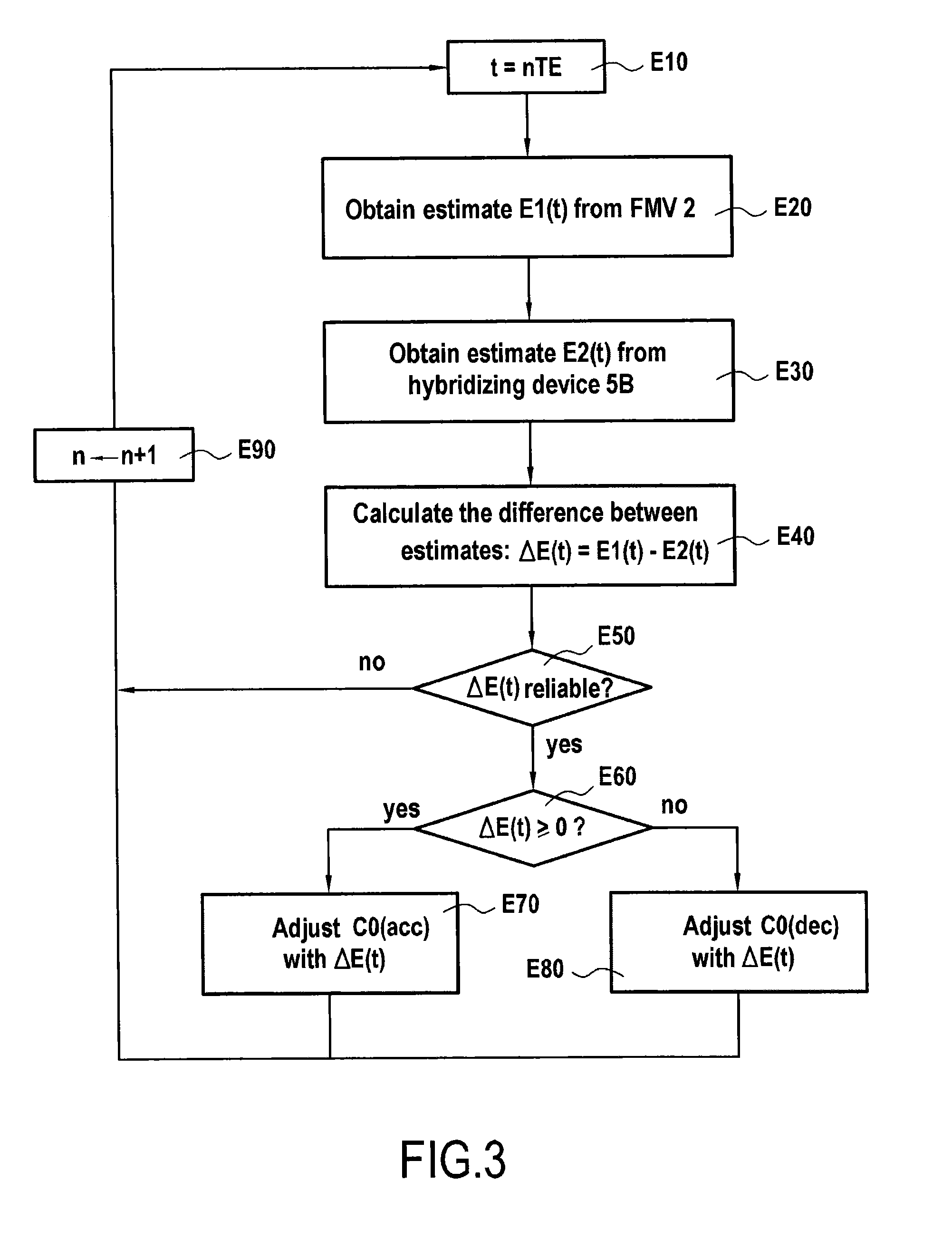
A method of adjusting a fuel flow rate in a turbine engine propelling an aircraft, including: obtaining a first estimate of a flow rate of fuel injected into a combustion chamber of the turbine engine propelling an aircraft and as delivered by a fuel metering device of the turbine engine; obtaining a second estimate of the fuel flow rate, which second estimate is more accurate than the first estimate for at least one range of fuel flow rate values and being delivered by an estimator device having a flow meter; and adjusting the fuel flow rate threshold value with help of a difference evaluated between the first estimate and the second estimate, the threshold value being for use in an open loop for regulating the turbine engine.

Description

BACKGROUND OF THE INVENTION[0001]The present invention relates to the general field of turbine engines and it applies in preferred manner to the field of aviation.[0002]The invention relates more particularly to regulating the flow rate of fuel to an aircraft turbine engine, such as a turbojet for example, during a transient stage of operation for the aircraft, such as a stage of acceleration or of deceleration.[0003]In known manner, the fuel flow rate for a turbojet is regulated for the purpose of ensuring that the mass flow rate of fuel injected into the combustion chamber of the turbojet during a stage of acceleration or of deceleration does not cross a certain limit value beyond which it is possible that the turbojet will malfunction. By way of example, such malfunctioning may be surging of a compressor of the turbojet during a stage of acceleration or burning out of the turbojet during a stage of deceleration.[0004]Nowadays, this regulation relies on an estimate of the mass flo...

Claims


Application Information

Patent Timeline
IPC IPC(8): F02C9/26
CPCF02C9/26F05D2270/309F05D2220/323F05D2270/114F05D2270/306F02C9/263F05D2270/044F02C9/32
Inventor JAVELOT, CHRISTOPHEDJELASSI, CEDRIKGAULLY, BRUNO ROBERTSYLLA, ISMAIL
Owner SN DETUDE & DE CONSTR DE MOTEURS DAVIATION S N E C M A
Learn More