
Visualizing sound with an electro-optical eardrum

a technology of electro-optical eardrum and visualizing sound, applied in the field of hearing systems, can solve the problems of not being able to use the existing devices summarized above in an educational setting to demonstrate hearing, educators have not addressed many of the problems, and have not addressed the problems of inadequately, to da

Inactive Publication Date: 2015-05-28
UNIVERSITY OF SCRANTON
View PDF2 Cites 3 Cited by
  • Summary
  • Abstract
  • Description
  • Claims
  • Application Information

AI Technical Summary

Benefits of technology

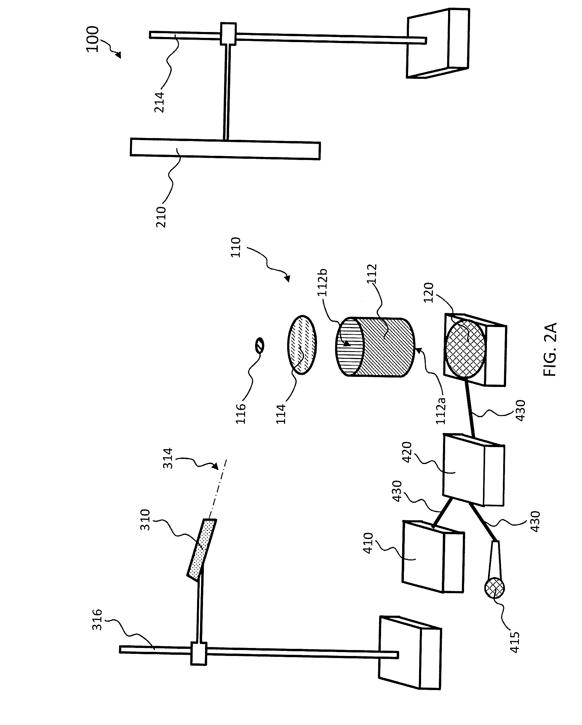
The present invention is a device called an electro-optical eardrum that helps deaf people see sound. This invention involves a special model of the ear canal that is placed over a speaker and has a mirror attached to it. A laser pointer shines light at the mirror, creating a pattern that is reflected on a screen. The system can also show how sensitive the person's ear is to different sounds. The invention is designed for use in an educational setting to help deaf or hearing-impaired people better understand and interpret music.

Problems solved by technology

Despite the existence of the devices summarized above, science educators have yet to address many of the problems that arise when attempting to teach deaf or hearing-impaired students.
None of the existing devices summarized above can be used in an educational setting to demonstrate hearing sensitivity to a deaf or hearing-impaired person.
Educators have inadequately addressed, to date, the problem of how they would include a deaf student in the experiment while the other students are listening to headphones to determine their personal hearing sensitivities.

Method used


Image

  • Visualizing sound with an electro-optical eardrum
  • Visualizing sound with an electro-optical eardrum
  • Visualizing sound with an electro-optical eardrum

Examples


example

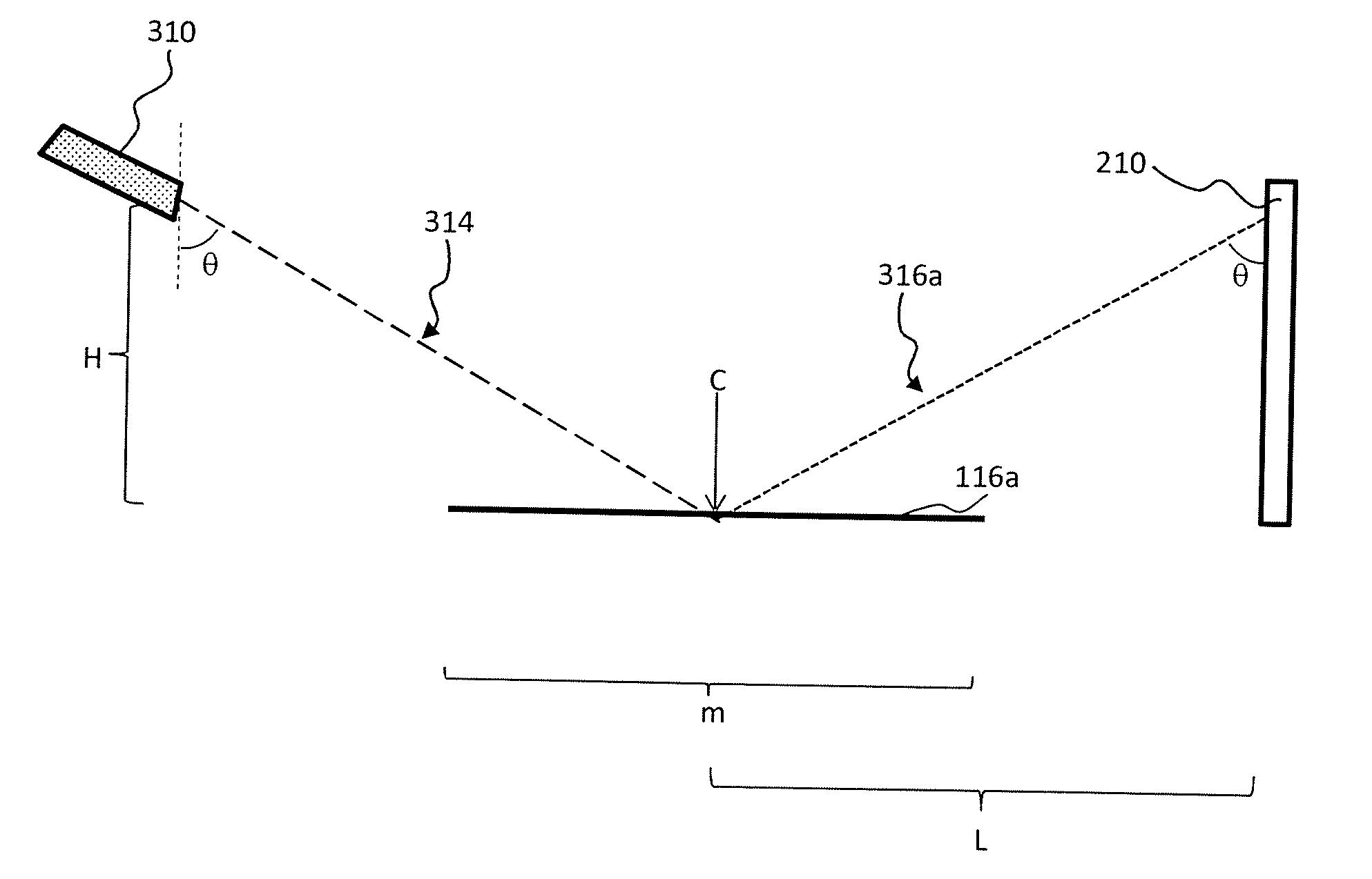
[0038]The following example is included to more clearly demonstrate the overall nature of the invention. This example is exemplary, not restrictive, of the invention. The example refers to FIGS. 4-6. In FIG. 4, the system 100 (illustrated, for example, in FIG. 2A) is depicted at equilibrium. In FIG. 5, the system 100 is depicted at the maximum amplitude of the membrane 114 (FIG. 2) when it deforms according to Mode (0, 1) (the top left image of FIG. 3). In FIG. 6, the system 100 is depicted at the maximum amplitude of the membrane 114 when it deforms according to Mode (1, 1) (the top right image of FIG. 3).

[0039]Referring to FIG. 4, the center C of the mirror 116 is placed at an equal horizontal distance L between the screen 210 and the laser pointer 310. The mirror 116 has a diameter m. The laser pointer 310 is placed at a height H above the center C of the mirror 116. The laser pointer 310 is oriented so that the light 314 emitted by the laser pointer 310 reaches the center C of t...


PUM


Abstract

An educational system for visualizing sound by a student in a laboratory. The system includes a speaker powered by an audio amplifier. A function generator or a microphone controls the amplitude and frequency of pressure waves originating from the speaker. A model of the ear canal is suspended over the speaker, the model having a plastic pipe with two open ends and a membrane stretched taut over one of the open ends with constant tension. A mirror is affixed to the membrane, creating a mass-loaded membrane. A laser pointer emits light directed toward the mirror. A screen receives a light reflection pattern created by the light reflected from the minor, with the model ear canal, speaker, membrane, and mirror placed equidistant between the screen and the laser pointer. The system is adapted to demonstrate hearing sensitivity to a deaf or hearing-impaired person in an educational setting.

Description

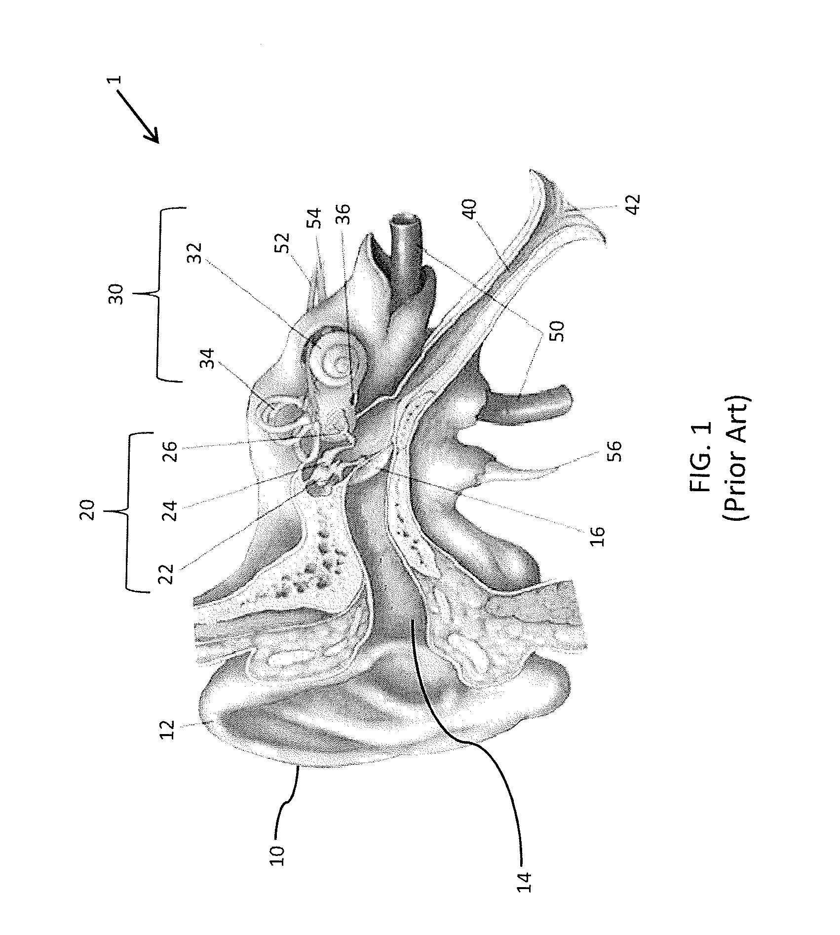
RELATED APPLICATION[0001]This application claims the benefit of priority to U.S. Provisional Patent Application Ser. No. 61 / 908,234, filed on Nov. 25, 2013, the contents of which are incorporated in this application by reference.TECHNICAL FIELD[0002]The present invention relates generally to hearing systems and, more particularly, to an electro-optical eardrum that allows the deaf or hearing-impaired to visualize sound.BACKGROUND OF THE INVENTION[0003]The purpose of the auditory system in mammals is to convert sound (pressure) waves into electrical signals that the brain can interpret. The human ear 1 is divided into the outer ear 10, the middle ear 20, and the inner ear 30 as shown in FIG. 1 and explained, for example, in Reece et al., Campbell Biology at pages 1090-94 (9th ed., Pearson Education Inc., 2011). The outer ear 10 includes the pinna 12, a curved external cartilage which “catches” sound waves and directs them into the auditory canal 14. At the end of the auditory canal 1...

Claims


Application Information

Patent Timeline
Patent Type & Authority Applications(United States)
IPC IPC(8): G09B23/32
CPCG09B23/32
Inventor TRUNCALE, NICHOLAS P.GRAHAM, MICHELLE
Owner UNIVERSITY OF SCRANTON
Learn More