
Header for implantable pulse generator and method of making same

Active Publication Date: 2015-05-21
DONATELLE PLASTICS
View PDF2 Cites 7 Cited by
  • Summary
  • Abstract
  • Description
  • Claims
  • Application Information

AI Technical Summary

Benefits of technology

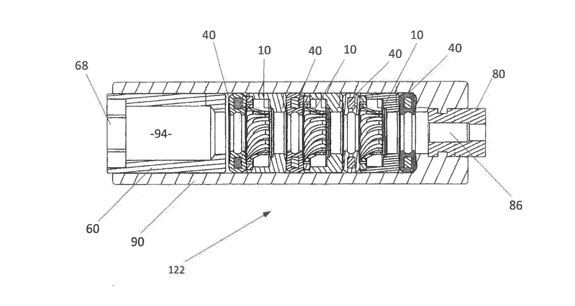
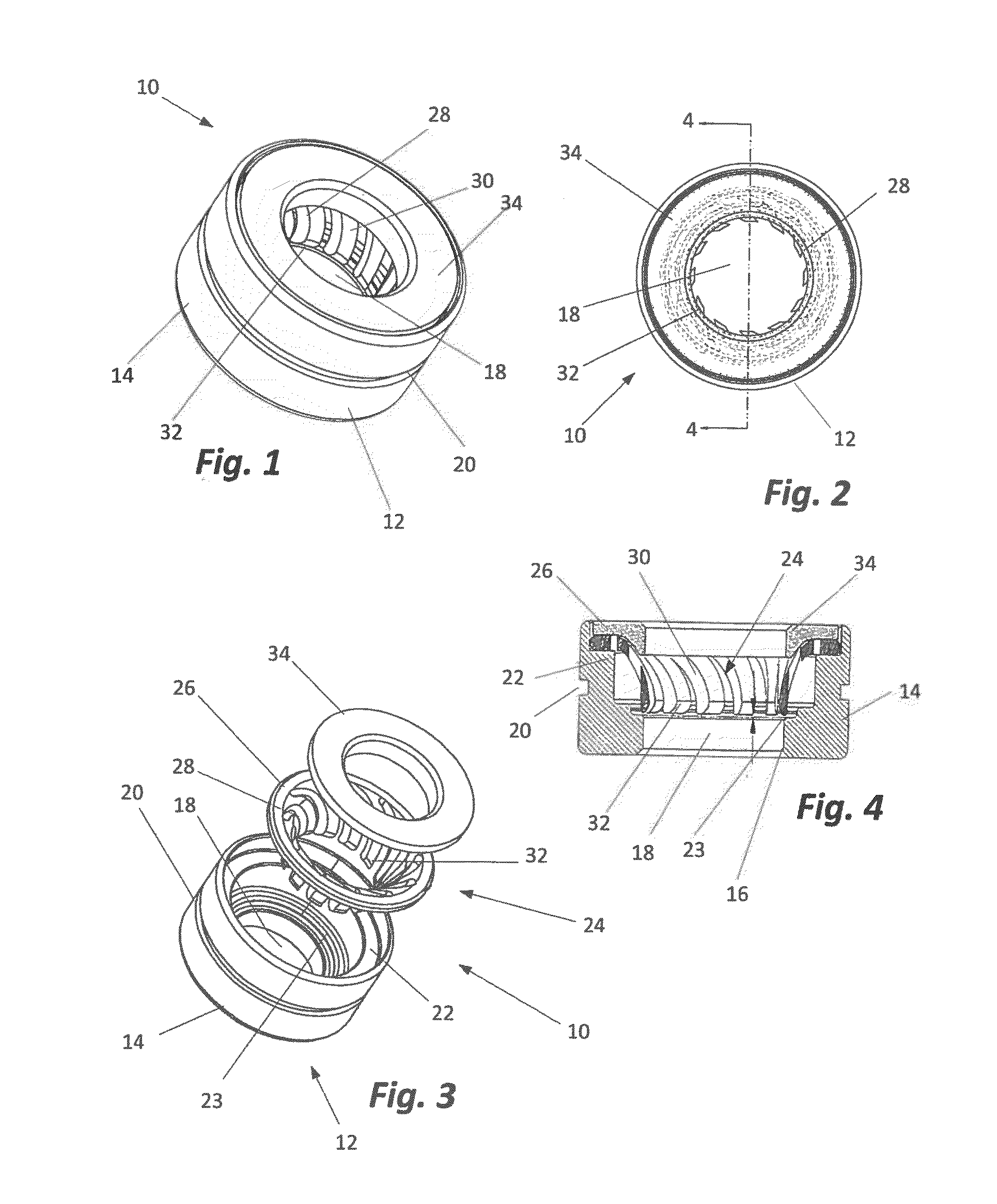
The invention provides a way to make a header for an implantable pulse generator with several advantages. The sleeve can have windows through which wires can be passed to connect to the spring contact rings. The strain relief and sleeve can be locked in position by moving them into the sleeve and twisting them together. The ring seals can have a rigid core to maintain a minimum distance between the spring contact rings and prevent deformation during overmolding. The spring contact rings have spiral, radial cut spring fingers that make them stronger and more robust. Overall, the invention provides a more efficient and reliable way to make headers for implantable pulse generators.

Problems solved by technology

ATP is only effective if the underlying rhythm is ventricular tachycardia, and is never effective if the rhythm is ventricular fibrillation.
Previous header designs and manufacturing techniques have resulted in difficulty in maintaining component alignment, spacing, and isolation.
Likewise, previous header designs and manufacturing techniques made it difficult, if not impossible, to adequately test the assembly before it was fully complete.
If testing demonstrates an issue exists with the header after manufacturing is complete, the entire header needs to be discarded and typically none of the components can be salvaged.
The inventors also believe previous devices and manufacturing methods create difficulty in maintaining the desired balance between mechanical and electrical properties.
Examples of deficiencies include: (1) a strong mechanical insertion force resulting in excessive pressure exerted on the inner seal and electrical components of the bore; (2) excessive electrical contact resulting in shorts or faults which can draw off potential battery power; (3) insufficient retention forces resulting in an electrode of the bore losing position or falling out of place; and (4) manufacturing tolerances which create challenges related to meeting the electrical and mechanical conformance requirements.
The tolerances of the electrode lead wires present further challenges with respect to the header's ability to achieve the desired electrical and mechanical responses.
The inventors believe these devices offer an adequate electrical connection, but are fragile in design.
Such connectors can be damaged or broken easily upon insertion of lead pins into the bore.
In addition, current designs are expensive to manufacture requiring multiple component pieces and challenging assembly steps driving up cost.
Prior art header designs also provide seals which are intended to isolate the electrical channels, but are subject to failure either during manufacture or as a result of the insertion or removal of lead pins.
These seals can also result in alignment problems which arise during overmolding, typically one of the last steps in the manufacturing process.
If during overmolding the molding pressures or temperatures deform the seals in an unintended manner, improper alignment of the components and improper sealing can occur.
While the resulting header will work, the header is expensive and time consuming to manufacture.
For the reasons set forth above, assembly of IPG devices is currently very labor-intensive and time-consuming, and requires skilled craftsmanship on the part of each person performing the assembly steps.
Problems associated with these techniques include: electrical leakage between components, electrical failures and excessive force required for inserting and withdrawing lead pins.
Such manufacturing techniques result in a high scrap rate and a high scrap cost, since failures are detected only after completion of whole device assembly.
Furthermore the final assembly is confined to a specific outer casting design.

Method used


Image

  • Header for implantable pulse generator and method of making same
  • Header for implantable pulse generator and method of making same
  • Header for implantable pulse generator and method of making same

Examples


Embodiment Construction

[0066]The following discussion is presented to enable a person skilled in the art to make and use the present teachings. Various modifications to the illustrated embodiments will be readily apparent to those skilled in the art, and the principles described herein may be applied to other embodiments and applications without departing from the present invention. Thus, the present invention is not intended to be limited to embodiments shown, but is to be accorded the widest scope consistent with the principles and features disclosed herein. The following detailed description is to be read with reference to the figures, in which like elements in different figures have like reference numerals. The figures, which are not necessarily to scale, depict selected embodiments and are not intended to limit the scope of the present invention. Skilled artisans will recognize many useful alternatives to the teachings and the examples provided herein falling within the scope of the invention exist a...


PUM

PropertyMeasurementUnit
Distanceaaaaaaaaaa
Strain pointaaaaaaaaaa

Abstract

A header for use in implantable pulse generator devices. The header is part of electrical connector assembly having one or more openings designed to receive the terminal pin of an electrical lead wire or electrode. The header is designed to provide and sustain long-term electrical and mechanical lead wire connections between the electrodes of a terminal pin and the implantable pulse generator device.

Description

CROSS-REFERENCED TO RELATED APPLICATIONS[0001]This application is a continuation-in-part of U.S. patent application Ser. No. 14 / 060,097 filed Oct. 22, 2013 which is a continuation of U.S. patent application Ser. No. 13 / 093,455, filed Apr. 25, 2011, now U.S. Pat. No. 8,666,494 granted on Mar. 4, 2014, which is a non-provisional application of Application No. 61 / 329,173, filed Apr. 29, 2010 and claims priority to that application which is also deemed to be incorporated by reference in its entirety in this application.STATEMENT REGARDING FEDERALLY SPONSORED RESEARCH OR DEVELOPMENT[0002]Not applicable.BACKGROUND OF THE INVENTION[0003]I. Field of the Invention[0004]The present invention relates to implantable pulse generators and, more particularly, implantable pulse generator headers and components of such headers. The present invention also relates to methods for manufacturing headers for implantable pulse generators.[0005]II. Discussion of Related Art[0006]In medical technology an imp...

Claims


Application Information

Patent Timeline
IPC IPC(8): A61N1/05H01B17/30
CPCH01B17/30A61N1/05A61N1/3752H01R13/5224H01R24/58H01R2201/12Y10T29/49016Y10T29/49176
Inventor VADLAMUDI, RAGHUIWEN, MATTHEW L.CALL, MATTHEW R.ZERBY, CHRISTOPHER M.FONDER, CLINT J.
Owner DONATELLE PLASTICS
Learn More