Self oscillating class D amplification device
- Summary
- Abstract
- Description
- Claims
- Application Information
AI Technical Summary
Benefits of technology
Problems solved by technology
Method used
Image

Examples
Example
DETAILED DESCRIPTION OF THE DRAWINGS
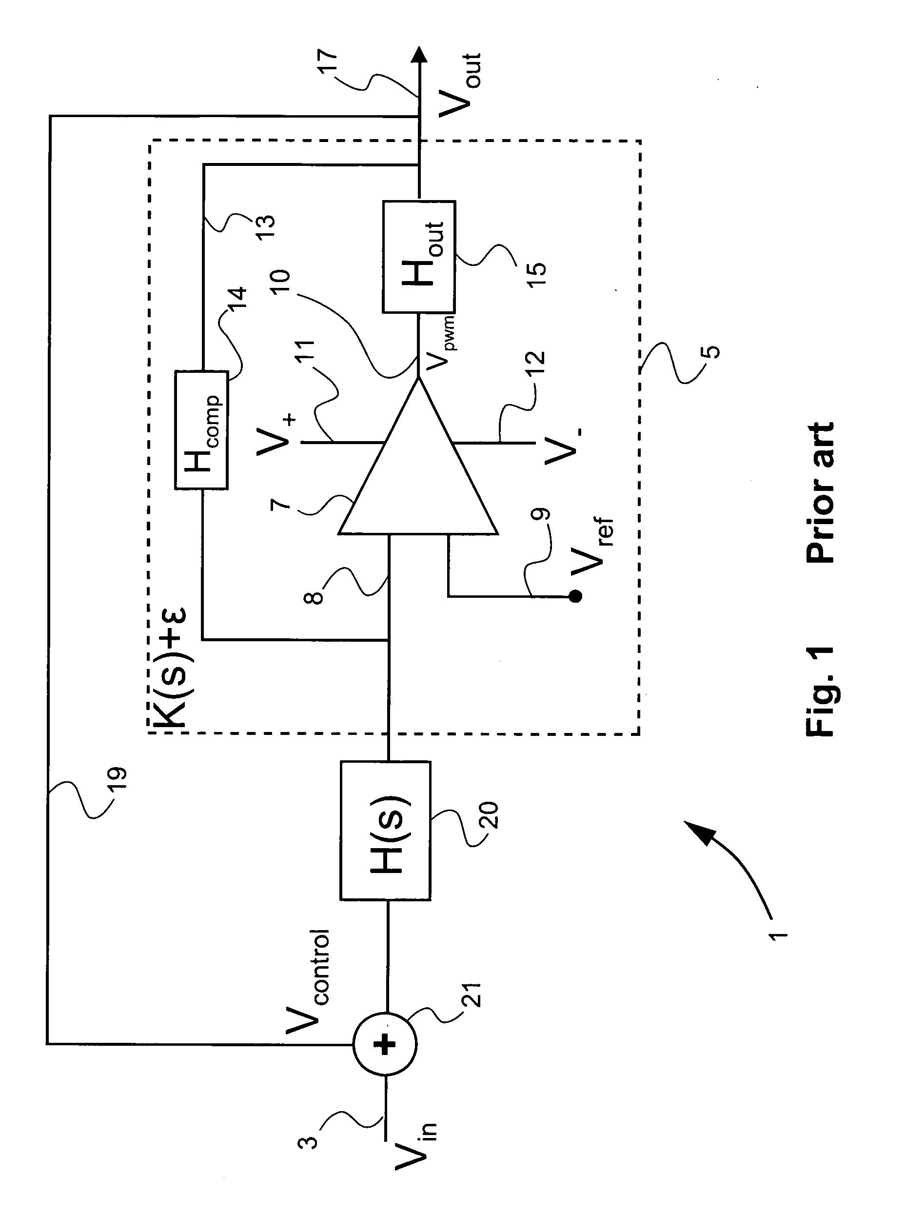
[0033]In FIG. 1 there is shown a high order controlled self-oscillating class D amplification device 1 according to prior art. In this illustration the device comprises an amplifier unit 5 which is based on a zero crossing detector unit, and comprises a comparator 7 and an output filter 15. Comparator 7 receives an incoming signal 8 which is compared to a reference signal Vref 9. Lead-lag compensation loop 13 is placed around comparator 7 and output filter 14. The lead-lag compensation loop 13, with filter Hcomp 14, together with low-pass filter 15 and the propagation delay of comparator 7, enables the amplifier unit 5 to operate in a self oscillating mode. Since the amplification device 1 is self-oscillating, the reference signal Vref usually will be a DC signal, in particular a reference potential, usually ground. Although it is under regular conditions and common applications not expected to be contributive, the skilled person has the liberty t...
PUM
 Abstract
Description
Claims
Application Information
 - R&D
- Intellectual Property
- Life Sciences
- Materials
- Tech Scout
- Unparalleled Data Quality
- Higher Quality Content
- 60% Fewer Hallucinations
Browse by: Latest US Patents, China's latest patents, Technical Efficacy Thesaurus, Application Domain, Technology Topic, Popular Technical Reports.
© 2025 PatSnap. All rights reserved.Legal|Privacy policy|Modern Slavery Act Transparency Statement|Sitemap|About US| Contact US: help@patsnap.com