
Non-contact egg identification system for determining egg viability, and associated method

a non-contact, egg identification technology, applied in the field of egg identification systems, can solve the problems of affecting the effectiveness of injected substances, the mortality rate of injected eggs or treated embryos, and the accuracy of conventional candling techniques, and similar levels of transmitted ligh

Active Publication Date: 2015-05-21
ZOETIS SERVICE LLC
View PDF22 Cites 10 Cited by
  • Summary
  • Abstract
  • Description
  • Claims
  • Application Information

AI Technical Summary

Benefits of technology

The present disclosure has various benefits, which are explained in detail herein.

Problems solved by technology

The selection of both the site and time of injection treatment can also impact the effectiveness of the injected substance, as well as the mortality rate of the injected eggs or treated embryos.
Unfortunately, such conventional candling techniques may have somewhat limited accuracy due to different categories of eggs having similar optical densities (e.g., live and rotted) resulting in similar levels of transmitted light.
However, some eggs identified as being live may in fact be non-live (e.g., rotted eggs, mid and late dead eggs).
However, these systems require the detection tooling to contact the eggs in order to create a mechanical light seal for detection purposes, which may present several problems.
Next, mechanical contact with the non-live eggs, particularly with the rotted eggs (which can explode when contacted), may undesirably introduce contamination into the detection system, which could potentially be transferred to subsequent live eggs during further processing.
Finally, the emitter-detector configurations in previous heartbeat detection systems are difficult to position mechanically to allow for desired throughput, wherein incomplete sealing may result in light leakage interfering with the desired transmitted signal.

Method used


Image

  • Non-contact egg identification system for determining egg viability, and associated method
  • Non-contact egg identification system for determining egg viability, and associated method
  • Non-contact egg identification system for determining egg viability, and associated method

Examples


Embodiment Construction

[0029]Various aspects of the present disclosure now will be described more fully hereinafter with reference to the accompanying drawings, in which some, but not all aspects of the disclosure are shown. Indeed, this disclosure may be embodied in many different forms and should not be construed as limited to the aspects set forth herein; rather, these aspects are provided so that this disclosure will satisfy applicable legal requirements. Like numbers refer to like elements throughout.

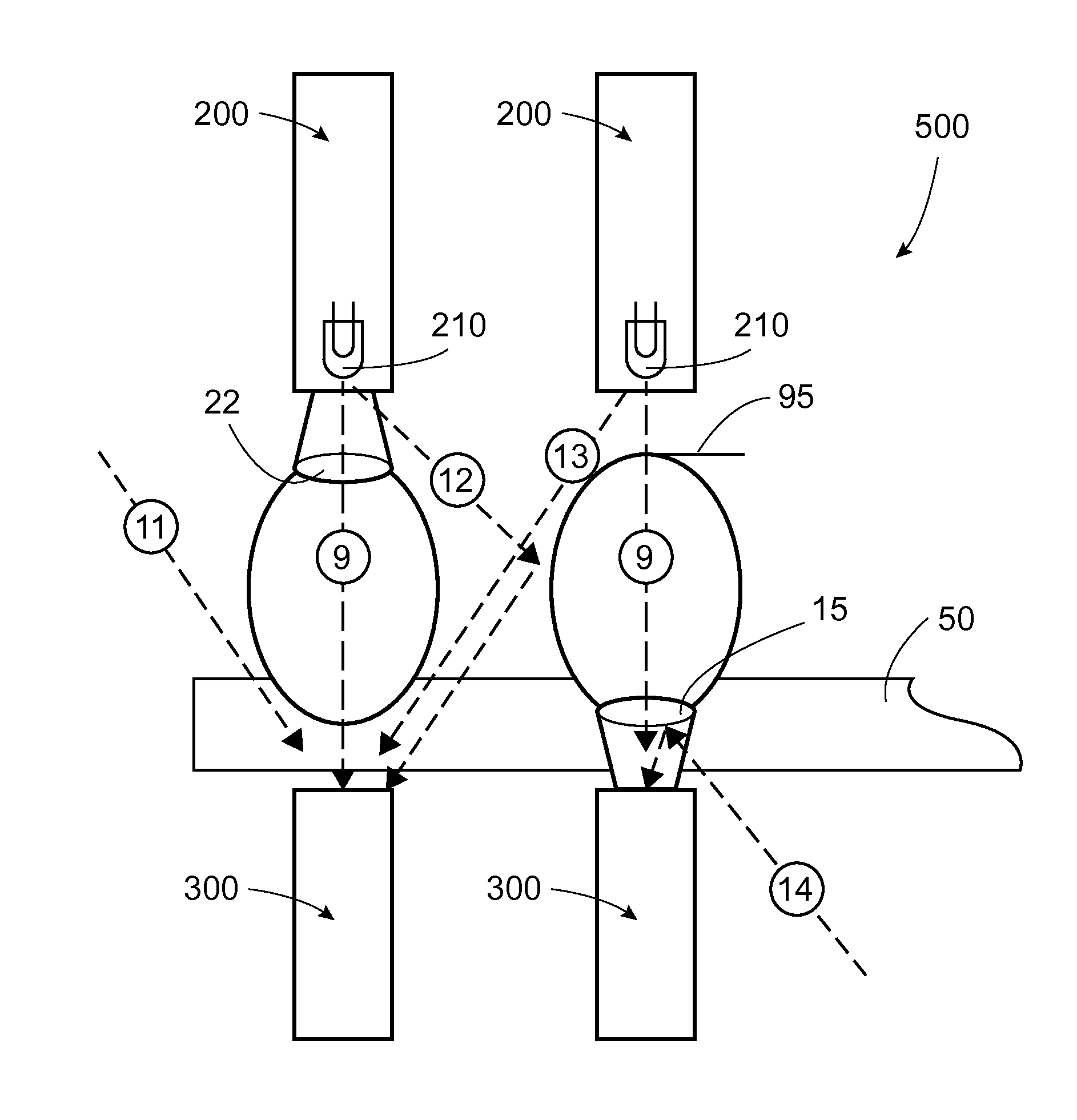
[0030]The present disclosure is directed to systems and methods for accurately determining the viability of a plurality of eggs in a high throughput manner without contacting the eggs as the eggs pass through an identification means. Passing of the eggs through the system in a non-contact or contactless manner provides many advantages, including maintaining stationary position of the detection system components to improve throughput and limiting contact with non-live eggs such as rotted eggs that may exp...


PUM

PropertyMeasurementUnit
wavelength rangeaaaaaaaaaa
diameteraaaaaaaaaa

Abstract

An egg identification system for determining viability of an avian egg is provided. Such a system includes an emitter assembly configured to emit electromagnetic radiation toward an egg. A detector assembly is axially aligned with the emitter assembly to detect electromagnetic radiation transmitted through the egg. The detector assembly is spaced-apart from the egg during operation thereof such that the detector assembly does not contact the egg. The detected electromagnetic radiation is used to generate an output signal. The output signal is processed to determine whether there exists a periodic variation or an aperiodic perturbation in an intensity of the electromagnetic radiation transmitted through the egg corresponding to action of a heart or embryo movement, wherein the existence of the periodic variation or aperiodic perturbation indicates that the egg is viable. An associated method is also provided.

Description

CROSS REFERENCE TO RELATED APPLICATION[0001]This application claims the benefit of U.S. Provisional Patent Application No. 61 / 905,385, filed Nov. 18, 2013, which is expressly incorporated herein by reference in its entirety.TECHNICAL FIELD[0002]The present disclosure generally relates to egg identification systems. More particularly, the present disclosure relates to a non-contact egg identification system capable of determining whether a viable embryo is present within an avian egg by using an emitter-detector system, and an associated method.BACKGROUND[0003]Discrimination between poultry eggs on the basis of some observable quality is a well-known and long-used practice in the poultry industry. “Candling” is a common name for one such technique, a term which has its roots in the original practice of inspecting an egg using the light from a candle. As is known to those familiar with eggs, although egg shells appear opaque under most lighting conditions, they are in reality somewhat...

Claims


Application Information

Patent Timeline
Patent Type & Authority Applications(United States)
IPC IPC(8): G01N33/08G01N21/59
CPCG01N33/08G01N2201/125G01N2201/062G01N21/59A01K43/00A61B5/024G01N21/3563A01K45/007A61B5/704A61B2503/40G01N21/85G01N33/085G01N21/951G01N2021/845
Inventor WALUKAS, JOEL JAMESKARIMPOUR, RAMIN
Owner ZOETIS SERVICE LLC
Learn More