
Continuous Tortilla Chip Cutter

a technology of continuous cutting and tortilla chips, which is applied in the field of assembly line food production machinery, can solve the problems of substantially imperfect chips, difficult to get all of the cuts to go through a common center, and relatively laborious process

Inactive Publication Date: 2015-05-21
CASA HERRARA
View PDF12 Cites 11 Cited by
  • Summary
  • Abstract
  • Description
  • Claims
  • Application Information

AI Technical Summary

Benefits of technology

The ultimate goal of a chopper / continuous tortilla chip system is to create tortilla chips without a "hem," which is a thick notch at the point of cutting that makes the chip stronger and harder to chew. This results in a more tender and fragile chip that is easier to chew and less likely to cause oral lacerations. The use of an industrial tumble dryer or a vibrating conveyor helps to separate the chips from each other and remove the stickiness of the chips caused by their moisture content.

Problems solved by technology

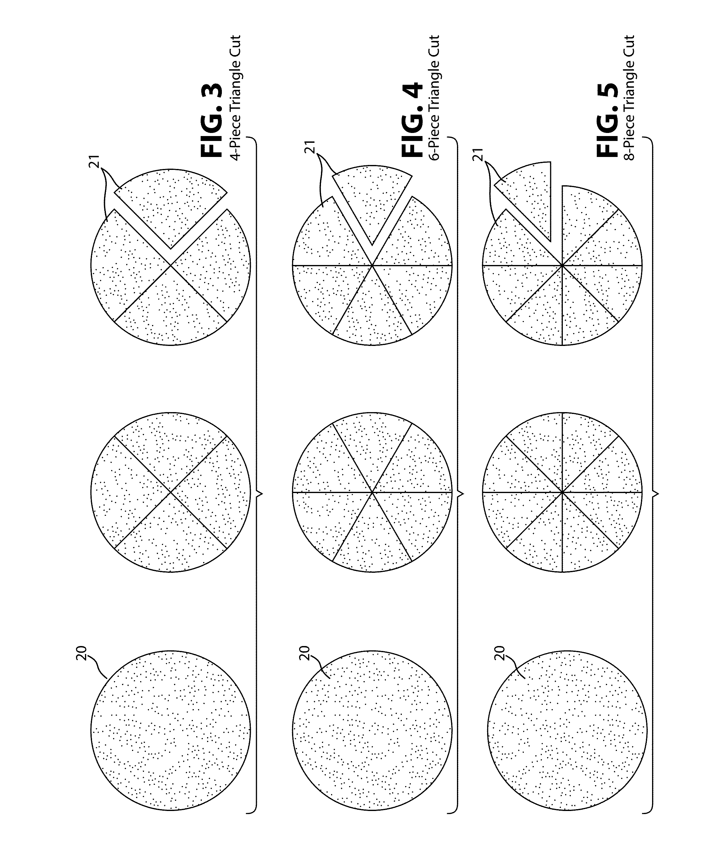
Hand-cutting is sometimes used to make triangular chips by using a knife to cross-cut the tortilla stack into four, six, or more pieces, as shown in FIGS. 2 to 5, but when cutting the tortilla into six or more pieces, which requires three or more cuts, it is somewhat difficult to get all of the cuts to go through a common center.
It can be done, but it is a relatively laborious process and the result is substantially imperfect chips.
The chips made in this manner are ideal for sale in grocery stores, convenience stores, vending machines, and the like, but are less than ideal for restaurant use.
Sheeted chips can be produced in mass quantities, but it is usually impractical to serve them fresh fried.
At least one drawback of this device is its complexity and its inapplicability to a continuous and automated cutting operation.
Unfortunately, due to the moisture content of the tortillas at the time of chopping (which is usually about 30%), the tortilla pieces “stick” together as the blade applies pressure and these pieces must be freed so that no two chips are “stuck” together.
Nonetheless, even with extensive cooling, sticking continues to be a problem due to the moisture content of the stacked tortillas and tumblers or shakers are often used to separate the pre-cuts from one another.
In addition, many of the prior art systems require manual placement of the stacks.

Method used


Image

  • Continuous Tortilla Chip Cutter
  • Continuous Tortilla Chip Cutter
  • Continuous Tortilla Chip Cutter

Examples


first preferred embodiment

General Operation

[0069]There are many possible embodiments of a Continuous Tortilla Chip Cutting System according to the present invention. FIGS. 6 and 7, for example, are schematic top and side views of a first preferred, albeit simplified embodiment of a Continuous Tortilla Chip Cutting System 10 for cutting tortillas 20 into pre-cuts 21. As shown in FIGS. 1 and 2, the system 10 receives the tortillas 20 from an upstream flatbread production line 30 which may be fully automated, manual, or some combination thereof. As shown, the system 10 comprises a conveyor 40 that is driven by a conveyor motor M40, a detector 50, a cutting mechanism 60 that is driven by a cutter motor M60, and a controller 70.

[0070]The goal is to form pre-cuts 21 that are distinct from one another, undamaged, and of consistent shape. The pre-cuts 21 formed by the system 10 are usually intended for frying, after further cooling or at some time in the future. For example, the producer may sell the box 80 of pre-c...

second preferred embodiment

[0075]FIGS. 8 and 9 are schematic top and side views of a second preferred embodiment of a continuous flat bread cutting apparatus 210 that is similar to the first preferred apparatus 10, but more specifically comprises a cutting mechanism 260 that formed from a pair of counter-rotating rollers 262, 264. As suggested by FIG. 9, the preferred upper roller 262 has a substantially smooth surface for cutting against (made e.g. of UHMW polyethylene), and the lower roller 264 has a plurality of blades 265 that rotate against the upper roller 262 (made e.g. of stainless steel). The key to consistent operation is to have the cutter roller 264 in a known starting position prior to the detection of each subsequent flatbread unit 20, and then to start its rotation at just the right time to cut each flatbread units 20 into correctly shaped pre-cuts21.

[0076]FIG. 10 is a perspective view of the cutting mechanism 260 used in the second preferred embodiment of FIGS. 8 and 9. As shown, the upper rol...

third preferred embodiment

[0081]FIG. 13 is a perspective view of a third preferred embodiment that is like the second preferred embodiment, but comprises a suitable frame 320 that supports two parallel conveyor belts 40 and two corresponding cutting mechanisms 260 for providing increased throughput when fed by a two-row tortilla production line.

[0082]FIGS. 14 to 16 are top, input end, and output end views, respectively, of the third preferred embodiment of FIG. 13.


PUM

PropertyMeasurementUnit
shapeaaaaaaaaaa
velocityaaaaaaaaaa
distanceaaaaaaaaaa

Abstract

A continuous tortilla chip cutting system where tortilla carried on a conveyor are continuously divided by a cutting mechanism into pre-cuts for frying into chips. A programmable controller drives a servo motor that moves an upper surface of the conveyor at a known velocity V, and a detector located above the conveyor at a known distance D from the cutting mechanism alerts the controller to the imminent arrival of the tortilla. The controller also controls a servo motor that actuates the cutting mechanism in a stop / start fashion. Based on the detection of the tortilla, the controller drives the servo motor associated with the cutting mechanism at just the right time and at just the right speed so that the cutter mechanism cuts each arriving tortilla into predictable sub-units called “pre-cuts” based on the velocity V of the conveyor belt, the detection of the flat bread unit carried by the conveyor, and the known distance between the moving flat bread unit and the cutter assembly.

Description

BACKGROUND OF THE INVENTION[0001]1. Field of the Invention[0002]This application relates generally to assembly line food production machinery and, more particularly, to a continuous tortilla chip cutter used, for example, for cutting tortilla chips from whole tortillas.[0003]2. Description of the Related Art[0004]FIGS. 1 to 5 show a flatbread unit 20 (i.e. a tortilla, pita bread, etc.), or a stack thereof, being processed into “pre-cuts”21 that will be fried and served. Restaurants and families alike have long been using a knife to hand-cut corn tortillas to make old fashioned fresh-fried tortilla chips. The hand-cut method works by using a knife to cut a tortilla 20, or short stack of tortillas (e.g. 5-7), into chip-shaped pieces 21 and then frying those pieces in hot oil. FIG. 1 shows a traditional tortilla cut that forms substantially-rectangular chips. FIG. 2 shows more closely spaced cuts that form thin strips that are suitable for tortilla soup. If done by hand, the cook would...

Claims


Application Information

Patent Timeline
Patent Type & Authority Applications(United States)
IPC IPC(8): B26D5/28B26D7/06B26D3/24A23L1/164B26D1/62
CPCB26D5/28A23L1/1645B26D1/62B26D3/24B26D7/0625A23V2002/00A23L7/13B26D1/40Y10T83/2196Y10T83/533Y10T83/541
Inventor MARTINEZ-MONTES, JOSE DE LA LUZ
Owner CASA HERRARA
Learn More