
Combination Air and Ground Source Heating and/or Cooling System

Active Publication Date: 2015-05-21
ATLAS L C HEATING & A C
View PDF1 Cites 3 Cited by
  • Summary
  • Abstract
  • Description
  • Claims
  • Application Information

AI Technical Summary

Benefits of technology

The present invention is a combination air and ground source heating and cooling system that can automatically switch between various operating modes. It provides enhanced mechanical and electrical controls to ensure durable and more efficient operation. The system includes an indoor unit, outdoor unit, and in-ground unit, which can be installed separately. The system also includes a flow connector, coupling, and controller to selectively operate in three different modes. The technical effects of the invention include improved efficiency, flexibility, and adaptability to advanced heat pump / air conditioner technology.

Problems solved by technology

Unfortunately, as many areas experience colder temperatures during certain periods of the year, an air source heat pump system will be subject to freezing and, therefore, is invariably used in combination with both a defrost system and an auxiliary heat source, such as an electric resistance heater element or an oil or gas burning system.
However, ground source heating systems are not without their drawbacks and are still typically supplemented by gas, oil or electric resistance heating units.
In particular, ground source heat pumps are more susceptible to counterproductive outputs, high head pressures, damage to overheating subterranean coils, flow restrictions and compressor failures based on excessive run times in either heating or cooling modes of operation.
Combination air and ground systems have been proposed but, to date, are not considered to be configured to operate at optimal efficiency.

Method used


Image

  • Combination Air and Ground Source Heating and/or Cooling System
  • Combination Air and Ground Source Heating and/or Cooling System
  • Combination Air and Ground Source Heating and/or Cooling System

Examples


Embodiment Construction

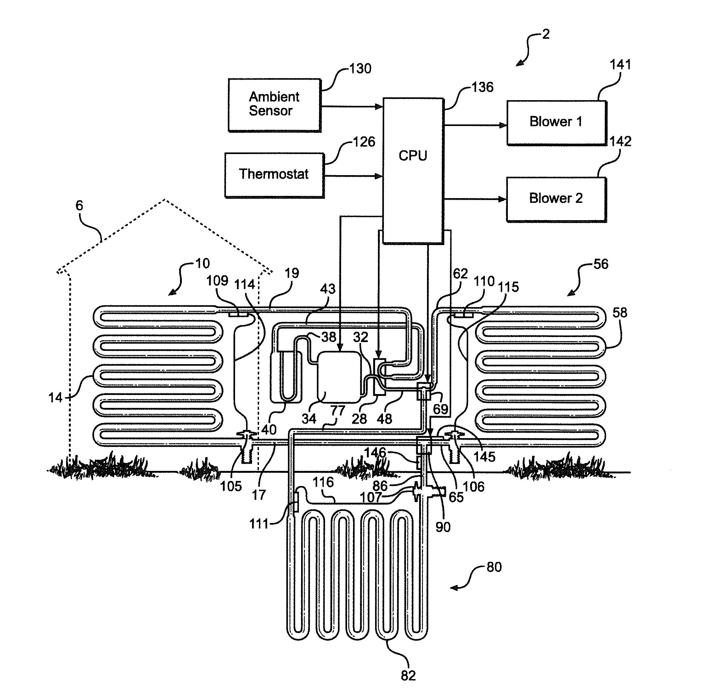
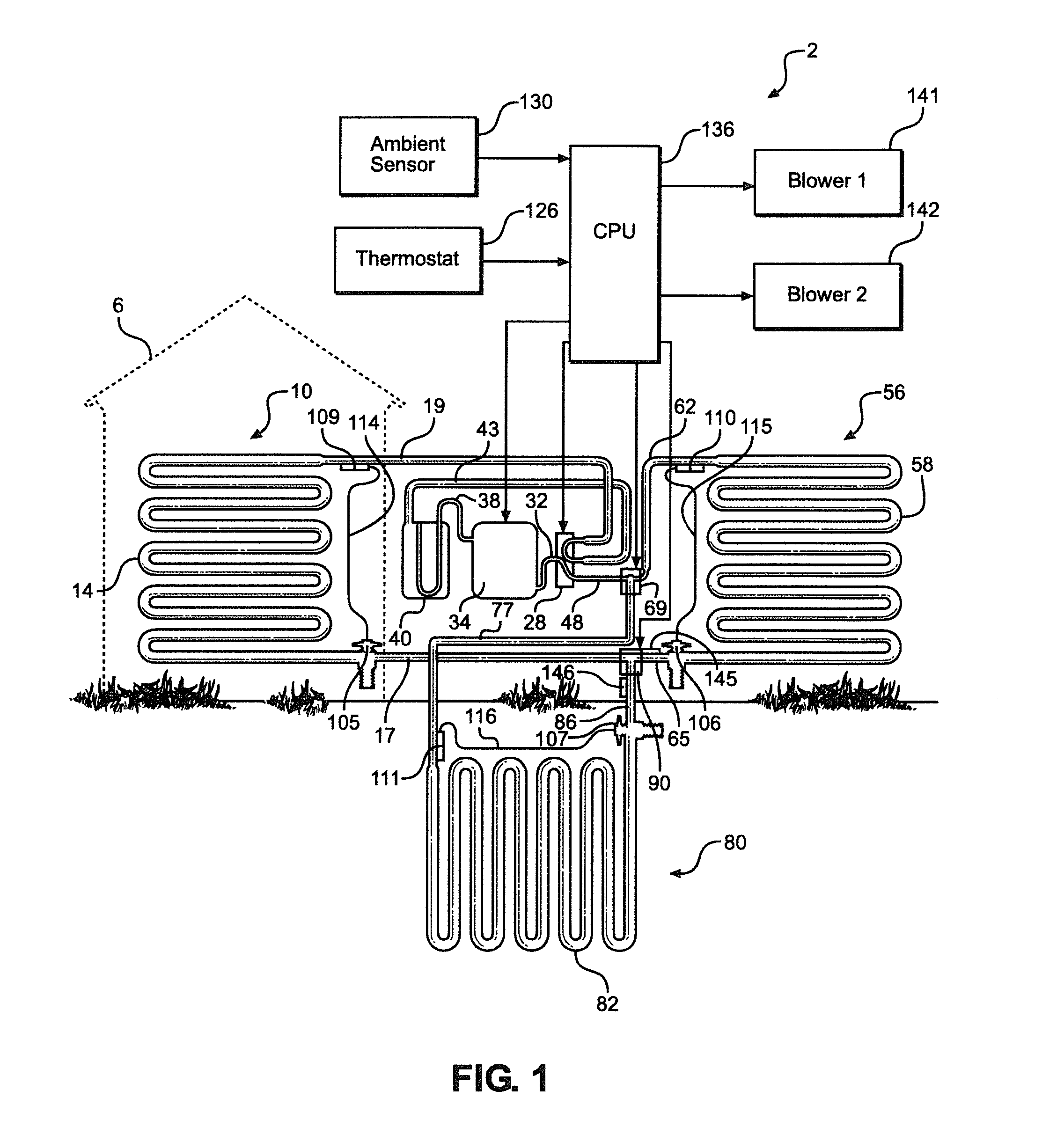
[0016]With initial reference to the schematic of FIG. 1, the combination heating and cooling system of the invention is generally indicated at 2. For purposes of describing the invention, particular reference will be made to combination heating and cooling system 2 functioning in a cooling mode of operation. However, as will also be pointed out further below, the flow through combination heating and cooling system 2 can be reversed in order to place system 2 in a heating mode.

[0017]As depicted, a building 6 is provided with an indoor heating / cooling unit 10 including an inside coil 14. In the cooling mode, inside coil 14 has an associated inlet line 17 and outlet line 19. Outlet line 19 leads to a reversing valve 28. In essence, reversing valve 28 can be shifted to change between heating and cooling modes of operation for system 2. However, as the structure and general operation of reversing valve 28 is known in the art, it will not be detailed further here. Reversing valve 28 recei...


PUM


Abstract

A combination air and ground source heating and / or cooling system. The system includes an indoor unit, an outdoor unit and an in-ground unit, each of which has a coil, an inlet line and an outlet line. The system also comprises a flow connector, a coupling and a controller. The controller is configured to control the flow connector and coupling so that the system is selectively operable in three different modes. In the first mode, refrigerant bypasses the coil of the outdoor unit, while, in the second mode, refrigerant bypasses the coil of the in-ground unit. In the third mode, refrigerant flows through the coils of the in-ground and outdoor units.

Description

CROSS-REFERENCE TO RELATED APPLICATIONS[0001]The present application claims the benefit of U.S. Provisional Application Ser. No. 61 / 907,101 filed Nov. 21, 2013 entitled “Combination Air and Ground Source Heating and / or Cooling System”.BACKGROUND OF THE INVENTION[0002]1. Field of the Invention[0003]The present invention is concerned with the field of heating, ventilation and air conditioning (HVAC) and, more particularly, with a heating and / or cooling system which relies on a combination of air and ground source units.[0004]2. Description of the Related Art[0005]In the HVAC field, both air and ground source heating systems are known and can represent efficient heating and cooling systems under ideal conditions. As such ideal conditions are rarely obtainable or sustainable, and each of air and ground source heating systems will present certain advantages, HVAC installers typically rely on prevailing environmental conditions in determining the type of system that is best suited for a p...

Claims


Application Information

Patent Timeline
IPC IPC(8): F25B27/00F25B30/06F24D15/04F25B49/02F24F5/00F25B29/00F25B41/00
CPCF25B27/00F25B29/003F25B30/06F25B41/003F24D2200/32F24F5/0046F24D15/04F24D2200/11F24D2200/123F25B49/02F24F2005/0057F24D5/12F25B13/00F25B2313/002F25B2313/0293F25B2313/0294F25B2700/2106Y02B10/40Y02B30/13
Inventor GAULT, ROBERT
Owner ATLAS L C HEATING & A C
Learn More