Plane-Type Speaker and AV Apparatus
a technology of av apparatus and a plane-type speaker, which is applied in the direction of diaphragm construction, transducer diaphragm, electromechanical transducer, etc., can solve the problems of poor sound quality characteristics of thin-type speakers, and achieve excellent sound quality characteristics, small thickness, and excellent sound quality characteristics
- Summary
- Abstract
- Description
- Claims
- Application Information
AI Technical Summary
Benefits of technology
Problems solved by technology
Method used
Image
Examples
first embodiment
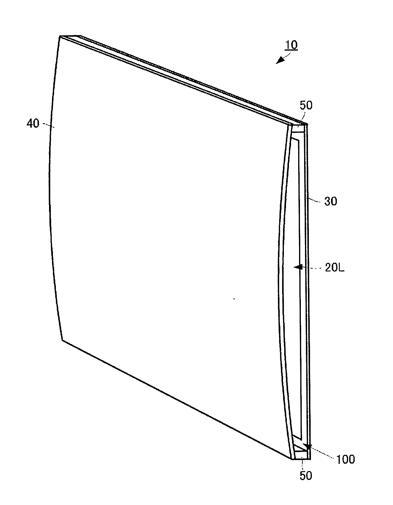
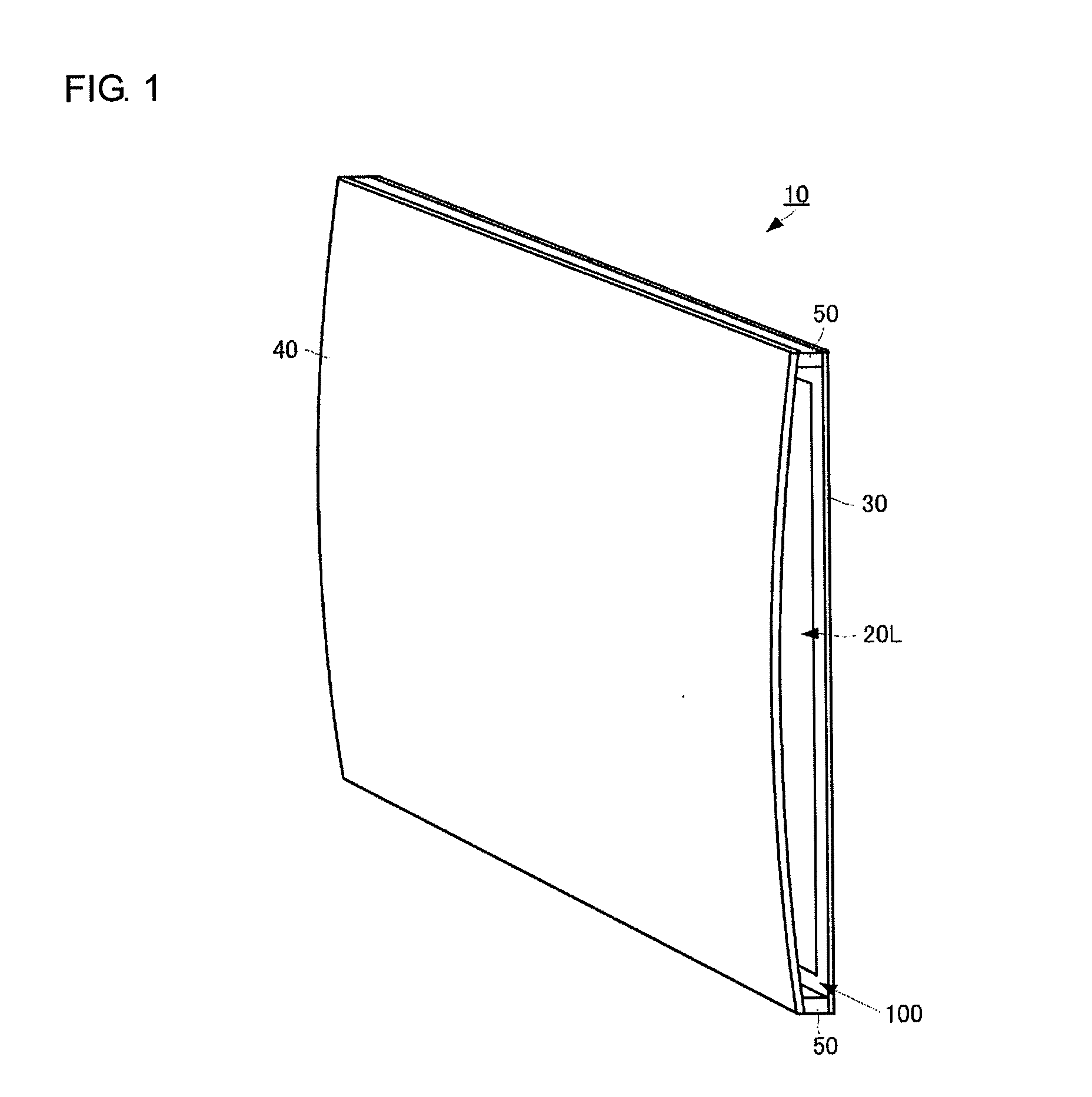
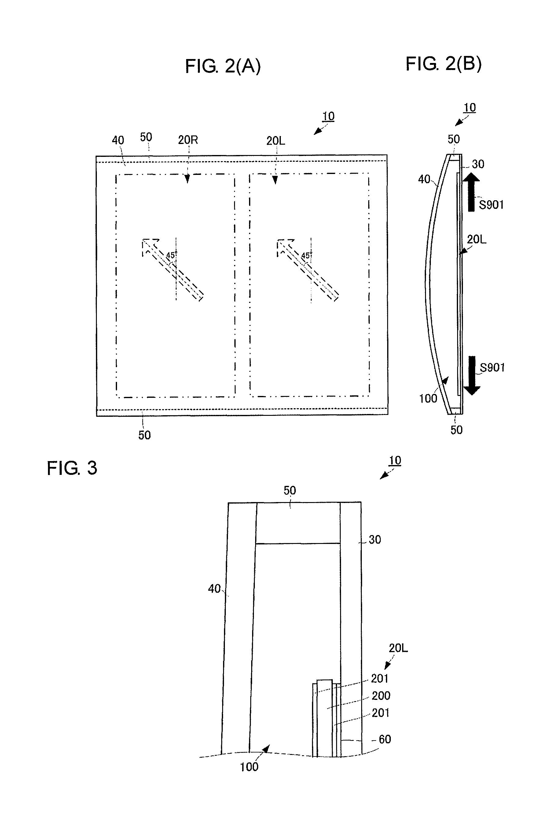
[0051]A plane-type speaker according to the present invention will be described, with reference to the drawings. FIG. 1 is a perspective view of the external appearance of the plane-type speaker 10 according to the present embodiment. FIG. 2(A) is a front view of the plane-type speaker 10, and FIG. 2(B) is a side view of the same. FIG. 3 is a partially-enlarged side view of the plane-type speaker 10.
[0052]The plane-type speaker 10 includes piezoelectric films 20R and 20L, an exciter film 30, an oscillation plate 40, and flame members 50. The piezoelectric films 20R and 20L are constituted by the same component, but they are attached to the exciter film 30 at different positions. Accordingly, they will be described in detail regarding their structure, with respect to the piezoelectric film 20L.
[0053]The piezoelectric film 20L includes a base film 200 having a rectangular shape in a plan view, and electrodes 201 formed on the opposing both main surfaces of the base film 200. The base ...
second embodiment
[0073]Next, a plane-type speaker will be described with reference to the drawings. FIG. 5 is a perspective view of the external appearance of a plane-type speaker 10A according to the present invention. FIG. 6 is a view for explaining the structure of the plane-type speaker 10A, wherein FIG. 6(A) illustrates a state before an oscillation plate 40A is secured thereto, and FIG. 6(B) illustrates a state where the oscillation plate 40A has been secured thereto.
[0074]The plane-type speaker 10A according to the present embodiment is different from the plane-type speaker 10 illustrated in the first embodiment, in that the oscillation plate 40A is secured to an exciter film 30 such that the main surface of the oscillation plate 40A is parallel with the main surface of the exciter film 30, but is the same in terms of the other structures.
[0075]The oscillation plate 40A is made of the same material as that of the oscillation plate 40 illustrated in the first embodiment, but it has preliminar...
third embodiment
[0079]Next, a plane-type speaker will be described with reference to the drawings. FIG. 8 is a perspective view of the external appearance of a plane-type speaker 10B according to the present embodiment. FIG. 9 is a view for explaining the structure of the plane-type speaker 10B, wherein FIG. 9(A) illustrates a side surface of an oscillation plate 40B in an exploded state, and an assembled state thereof, FIG. 9(B) illustrate a state where the oscillation plate 40B is secured, and FIG. 9(C) illustrates a state where the oscillation plate 40B has been secured.
[0080]The oscillation plate 40B is constituted by a main flat plate 400, and a pair of auxiliary plates 401. The main flat plate 400 is made of the same material and has the same shape as that of the oscillation plate 40 illustrated in the first embodiment. The auxiliary plates 401 are placed on the opposite ends of the main flat plate 400 in the longitudinal direction, namely near the two end sides thereof which are orthogonal ...
PUM
 Abstract
Description
Claims
Application Information
 - Generate Ideas
- Intellectual Property
- Life Sciences
- Materials
- Tech Scout
- Unparalleled Data Quality
- Higher Quality Content
- 60% Fewer Hallucinations
Browse by: Latest US Patents, China's latest patents, Technical Efficacy Thesaurus, Application Domain, Technology Topic, Popular Technical Reports.
© 2025 PatSnap. All rights reserved.Legal|Privacy policy|Modern Slavery Act Transparency Statement|Sitemap|About US| Contact US: help@patsnap.com


