
High Efficiency Interleaved Solar Power Supply System

a solar power supply and high efficiency technology, applied in the direction of a dc network circuit arrangement, semiconductor device, etc., can solve the problems of increasing reducing the cost of solar energy, so as to achieve high efficiency, improve the operation efficiency, and improve the effect of operation efficiency

Active Publication Date: 2015-05-14
AMPT
View PDF7 Cites 23 Cited by
  • Summary
  • Abstract
  • Description
  • Claims
  • Application Information

AI Technical Summary

Benefits of technology

The invention aims to provide better and more efficient power sources. This includes providing string of power sources, such as in solar installations. It also aims to provide higher operational voltage levels, while keeping them within regulatory limits. The invention also reduces inductance, capacitance, and energy storage at both the input and output levels. This results in less ripple in output and improved performance for electrical circuits operating on solar or other power sources.

Problems solved by technology

One aspect that has proven particularly challenging is the ability to harvest the energy efficiently across the entire power spectrum desired.
Because the influx of solar energy can vary and because the photovoltaic effect itself can vary, electrical challenges exist that to some degree remain.
In addition to the technical issues, regulatory limits such as desirable for safety and the like can also pose challenges.
In addition, the combination of photovoltaic sources such as in the strings of panels or the like combines to make efficient harvesting of the energy an issue.
This seeming paradox is an issue that remains challenging for those in the field.
Similarly the desire to generate more and more power such as through larger strings of panels has become an issue due to regulatory limits and the like.

Method used


Image

  • High Efficiency Interleaved Solar Power Supply System
  • High Efficiency Interleaved Solar Power Supply System
  • High Efficiency Interleaved Solar Power Supply System

Examples


Embodiment Construction

[0020]As mentioned earlier, the present invention includes a variety of aspects, which may be combined in different ways. The following descriptions are provided to list elements and describe some of the embodiments of the present invention. These elements are listed with initial embodiments, however it should be understood that they may be combined in any manner and in any number to create additional variations. The variously described examples and preferred embodiments should not be construed to limit the present invention to only the explicitly described systems, techniques, and applications. Further, this description should be understood to support and encompass descriptions and claims of all the various embodiments, systems, techniques, methods, devices, and applications with any number of the disclosed elements, with each element alone, and also with any and all various permutations and combinations of all elements in this or any subsequent application.

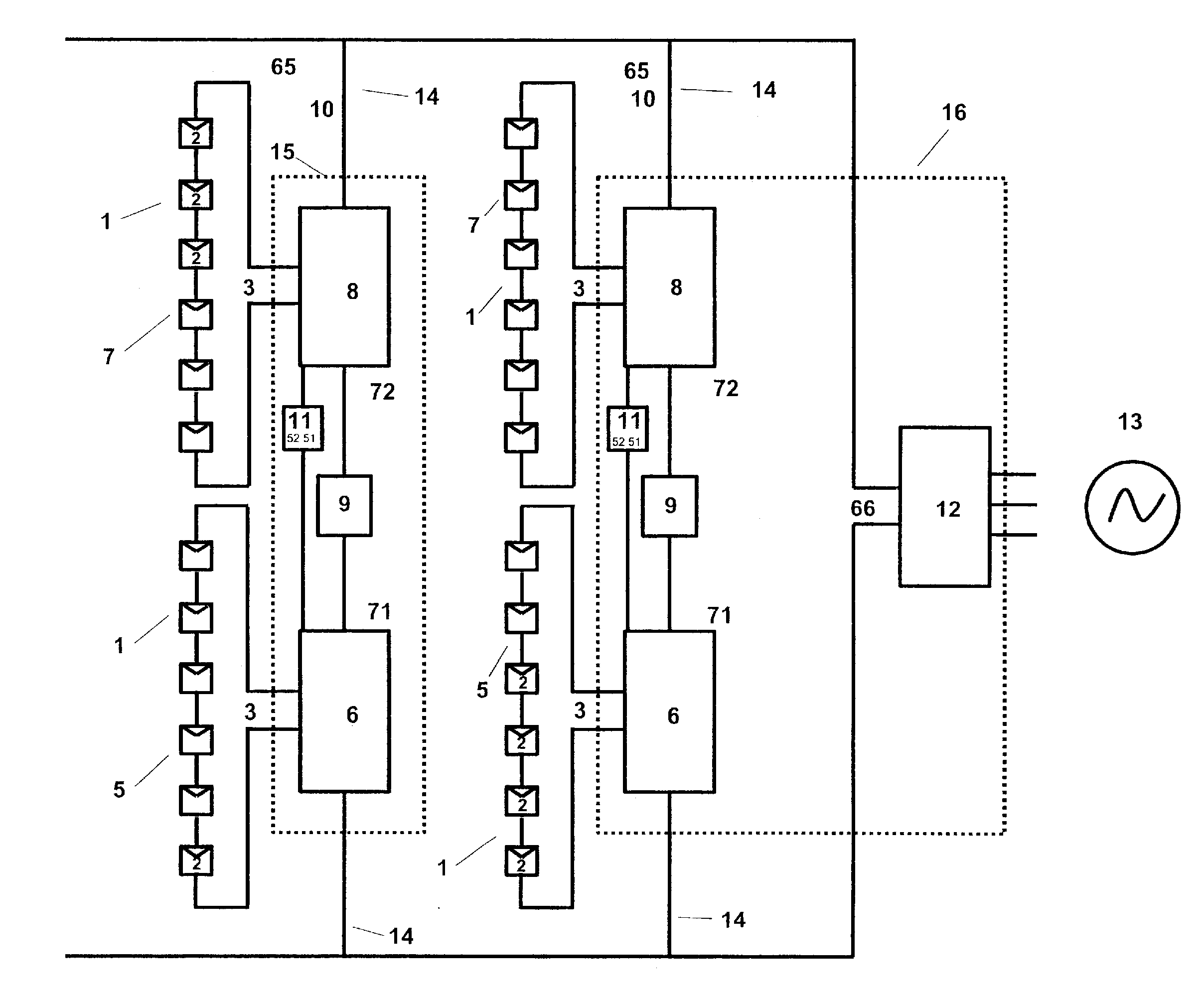
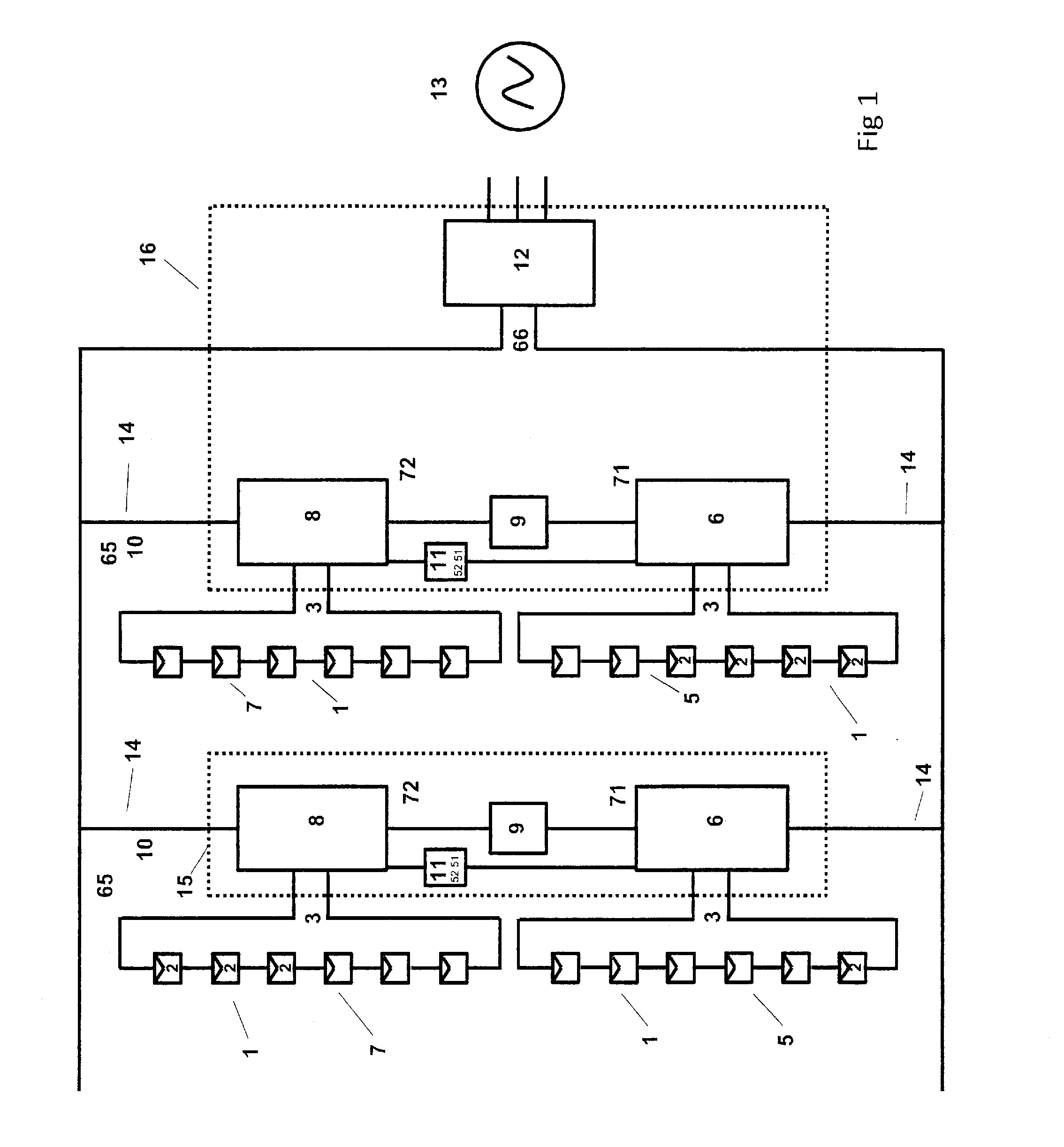
[0021]As shown in FIG. 1...


PUM


Abstract

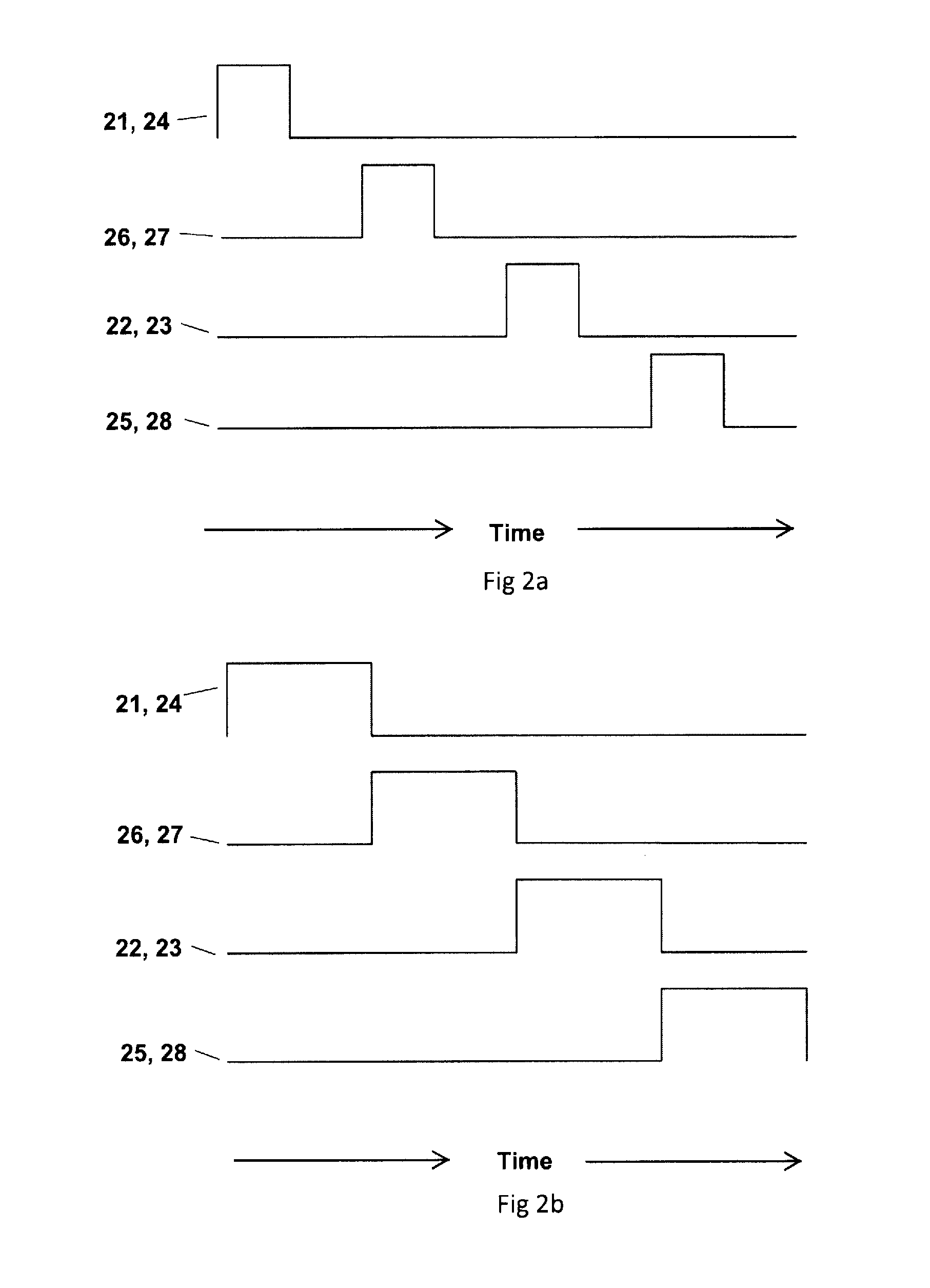
A high efficiency solar power system combining photovoltaic sources of power (1) can be converted by a base phase DC-DC photovoltaic converter (6) and an altered phase DC-DC photovoltaic converter (8) that have outputs combined through low energy storage combiner circuitry (9). The converters can be synchronously controlled through a synchronous phase control (11) that synchronously operates switches to provide a conversion combined photovoltaic DC output (10). Converters can be provided for individual source conversion or phased operational modes, the latter presenting a combined low photovoltaic energy storage DC-DC photovoltaic converter (15) at string or individual panel levels.

Description

I. TECHNICAL FIELD[0001]The present invention focuses on the field of providing solar power including but not limited to residential and commercial power systems and arrays. In particular it relates to processes, devices, and circuitry that can provide such power in a more efficient manner. It also can find application in general power systems that have some of the more fundamental attributes of solar power sources with the same effects.II. BACKGROUND[0002]The value of solar power for society has been known for many years. It offers clean energy but requires harnessing the energy and feeding it into electrical grid or other load. Efficiency in generation is of particular interest. One aspect that has proven particularly challenging is the ability to harvest the energy efficiently across the entire power spectrum desired. Because the influx of solar energy can vary and because the photovoltaic effect itself can vary, electrical challenges exist that to some degree remain. In addition...

Claims


Application Information

Patent Timeline
Patent Type & Authority Applications(United States)
IPC IPC(8): H02J1/00H01L31/02H02M1/00
CPCH01L31/02021H02J1/00H01L31/02008H02J1/102H02J2300/24H02J3/381Y02E10/56H02J3/46H02M1/0067H02M1/0077H02J3/38H02S40/30
Inventor LEDENEV, ANATOLI
Owner AMPT
Learn More