Wireless power transmitting apparatus and control method for such apparatus

a technology of power transmission apparatus and control method, which is applied in the direction of charging stations, electric devices, transportation and packaging, etc., can solve problems such as horizontal position deviation

Inactive Publication Date: 2015-05-14
PIONEER CORP
View PDF5 Cites 12 Cited by
  • Summary
  • Abstract
  • Description
  • Claims
  • Application Information

AI Technical Summary

Benefits of technology

[0033]The above object of the present invention can be solved by a wireless power feeding system comprising an alternating current power supply which generates an alternating current power, a power transmission coil which is electrically connected to the alternating current power supply, and a power reception coil which receives electric power in a wireless manner by electromagnetic induction from the power transmission coil, said wireless power feeding system is provided with a fixed capacitance capacitor which is electrically connected in parallel with one of the power transmission coil and the power reception coil, a variable capacitance capacitor which is electrically connected in series with the other one of the power transmission coil and the power reception coil, and a capacitance controlling device which controls a capacitance value of the variable capacitance capacitor to reduce a phase difference between a voltage phase and a current phase of the alternating current power.
[0034]According to the wireless power feeding system of the present invention, as in the wireless power transmitting apparatus and the wireless power receiving apparatus of the present invention described above, the power transmission can be efficiently performed even if the extent of the magnetic coupling (or the coupling coefficient) between the power transmission coil and the power reception coil changes.

Problems solved by technology

Moreover, there is a possibility that there may be a horizontal positional deviation between the power feeding side circuit and the power receiving side circuit due to a position at which a driver stops the electric vehicle.

Method used


Image

  • Wireless power transmitting apparatus and control method for such apparatus
  • Wireless power transmitting apparatus and control method for such apparatus
  • Wireless power transmitting apparatus and control method for such apparatus

Examples


first embodiment

[0053]A first embodiment of the wireless power feeding system of the present invention will be explained with reference to FIG. 1 to FIG. 9.

[0054](Configuration of Wireless Power Feeding System)

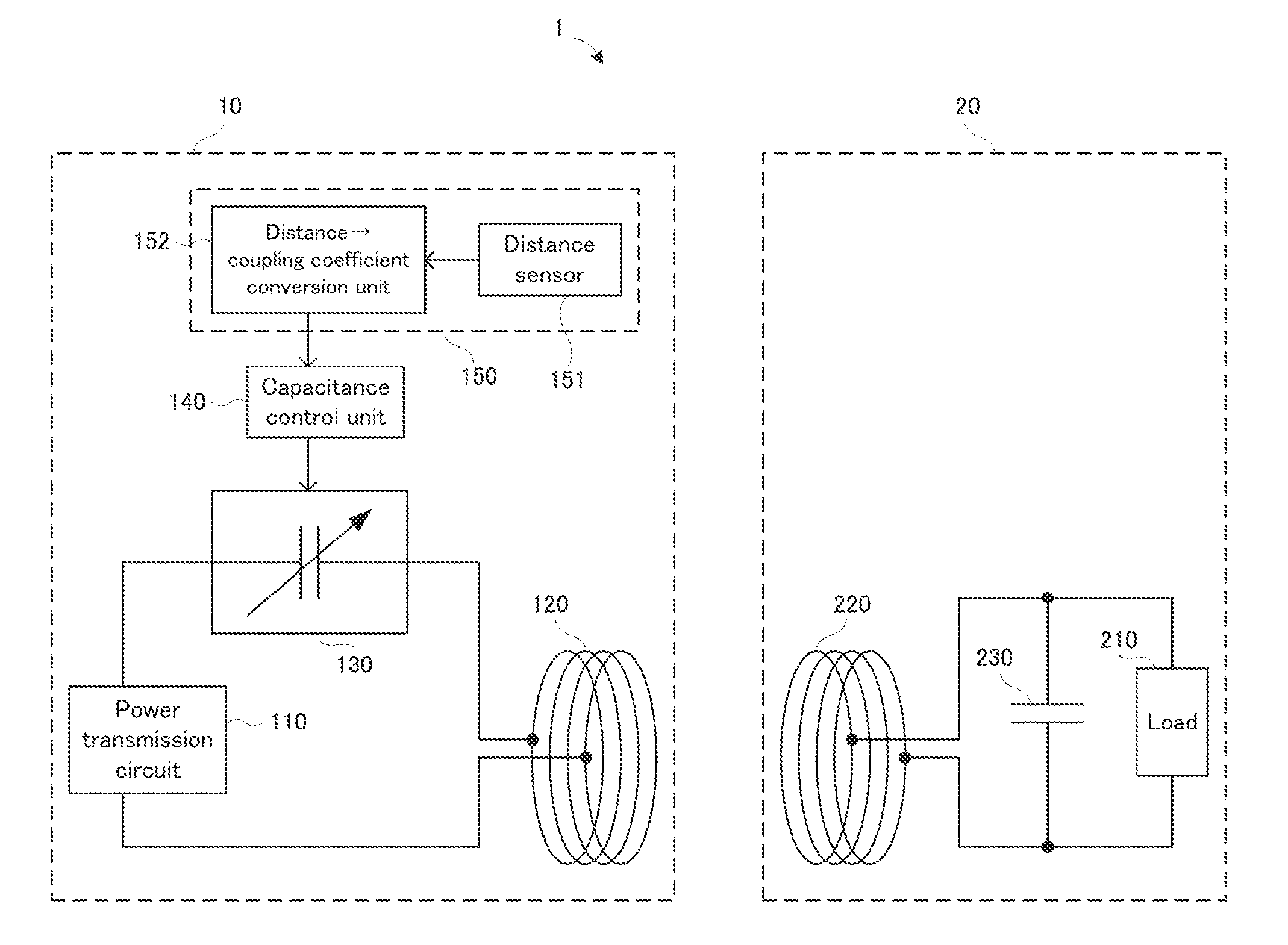
[0055]A configuration of a wireless power feeding system in the first embodiment will be explained with reference to FIG. 1. FIG. 1 is a block diagram illustrating the configuration of the wireless power feeding system in the first embodiment.

[0056]In FIG. 1, a wireless power feeding system 1 is provided with a power transmitting apparatus 10 and a power receiving apparatus 20.

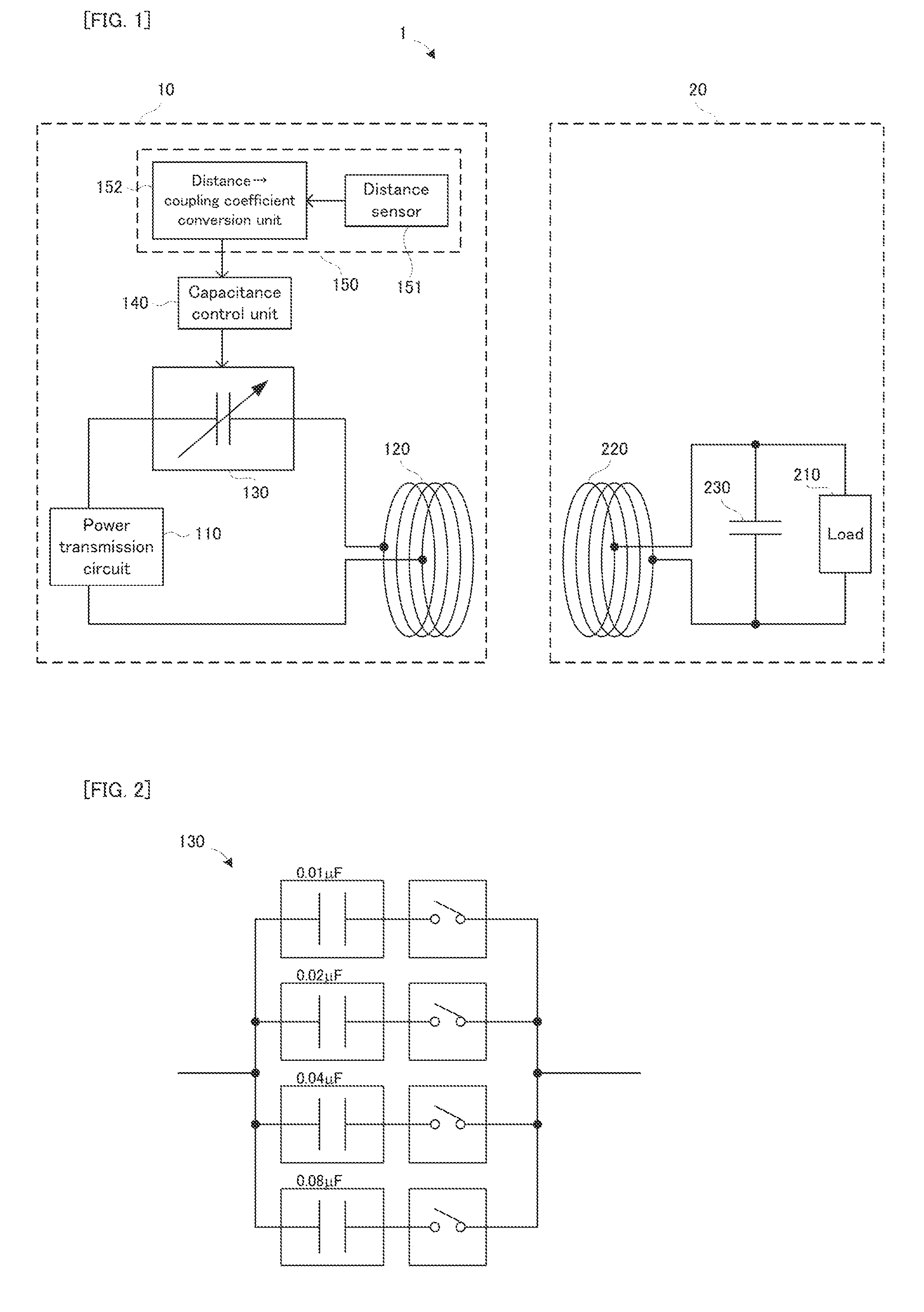
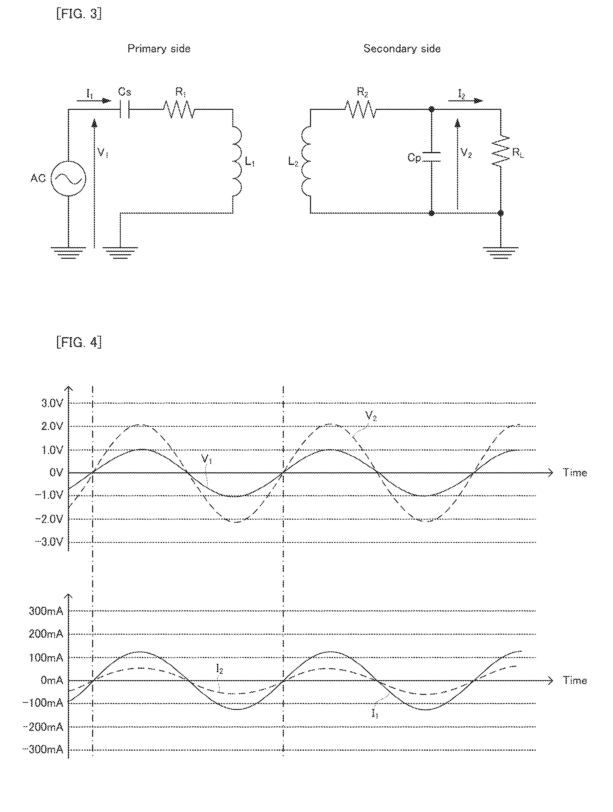
[0057]The power transmitting apparatus 10 is provided with (i) a power transmission circuit 110 including an alternating current power supply which generates alternating current power (not illustrated), (ii) a power transmission coil 120 electrically connected to the power transmission circuit 110, (iii) a variable capacitance capacitor 130 electrically connected in series with the power transmission coil 120, (iv) a ca...

second embodiment

[0082]A second embodiment of the wireless power feeding system of the present invention will be explained with reference to FIG. 10. The second embodiment has the same configuration as that of the first embodiment, except that the configuration of the wireless power feeding system is partially different. Thus, in the second embodiment, a duplicated explanation of the first embodiment will be omitted, and common parts have the same reference numerals on the drawings. Basically, only a different point will be explained with reference to FIG. 10. FIG. 10 is a block diagram illustrating the configuration of the wireless power feeding system in the second embodiment, to the same effect as in FIG. 1.

[0083]In FIG. 10, the coupling coefficient estimation unit 150 is further provided with an imaging device 154 which is arranged, for example, on a surface of the power transmission coil 120 opposed to the power reception coil 220 and in the vicinity of the center of the power transmission coil...

third embodiment

[0088]A third embodiment of the wireless power feeding system of the present invention will be explained with reference to FIG. 11. The third embodiment has the same configuration as that of the first embodiment, except that the configuration of the wireless power feeding system is partially different. Thus, in the third embodiment, a duplicated explanation of the first embodiment will be omitted, and common parts have the same reference numerals on the drawings. Basically, only a different point will be explained with reference to FIG. 11. FIG. 11 is a block diagram illustrating the configuration of the wireless power feeding system in the third embodiment, to the same effect as in FIG. 1.

[0089]In FIG. 11, the power receiving apparatus 20 is further provided with a voltage sensor 241 which measures a voltage value of the power receiving apparatus 20, a current sensor 242 which measures a current value of the power receiving apparatus 20, and a wires interface (I / F) unit 243 which t...


PUM


Abstract

A wireless power transmitting apparatus (10) is a wireless power transmitting apparatus which transmits electric power in a wireless manner by electromagnetic induction to a power receiving apparatus (20) which is provided with a power reception coil (220) and a fixed capacitance capacitor (230) electrically connected in parallel with the power reception coil. The wireless power transmitting apparatus is provided with: an alternating current power supply (110) which generates alternating current power; a power transmission coil (120) which is electrically connected to the alternating current power supply; a variable capacitance capacitor (130) which is electrically connected in series with the power transmission coil; and a capacitance controlling device (140) which controls a capacitance value of the variable capacitance capacitor to reduce a phase difference between a voltage phase and a current phase of the alternating current power.

Description

TECHNICAL FIELD[0001]The present invention relates to a wireless power transmitting apparatus, a wireless power receiving apparatus, and a wireless power feeding system which transmit and receive electric power in a wireless manner.BACKGROUND ART[0002]As this type of apparatus, there is proposed, for example, a wireless feeding apparatus which is provided with a serial capacitor electrically connected in series with a primary coil (or a power transmission coil) driven by an alternating current power supply, and a parallel-connected capacitor electrically connected in parallel with a secondary coil (or a power reception coil). This is referred to as a primary serial and secondary parallel resonance capacitor type. In this type, a capacitance value Cp of the parallel-connected capacitor on the secondary side is set to a value which resonates with the sum of excitation reactance x0 and leakage reactance x2 on the secondary side at drive frequency of a power supply (ω0) (Equation 1), an...

Claims


Application Information

Patent Timeline
Patent Type & Authority Applications(United States)
IPC IPC(8): H02J5/00B60L11/18H02J17/00
CPCH02J5/005B60L11/18H02J17/00Y02T10/7072Y02T90/14B60L53/122B60L53/126H02J2310/48Y02T10/70H02J50/90H02J50/12Y02T90/12
Inventor SUZUKI, MASAMIURUSHIBATA, EIICHIIWAWAKI, KEISUKE
Owner PIONEER CORP
Why Eureka
Try Eureka