
Multi-chamber, Multi-formulation Fluid Delivery System

a fluid delivery system and multi-formulation technology, applied in the field of multi-chamber fluid delivery systems, can solve the problems of difficult combining of levamisole and water-soluble anthelmintics (e.g. levamisole), and achieve the effect of reducing the requirements of squeeze strength

Active Publication Date: 2015-05-14
MERIAL INC
View PDF17 Cites 37 Cited by
  • Summary
  • Abstract
  • Description
  • Claims
  • Application Information

AI Technical Summary

Benefits of technology

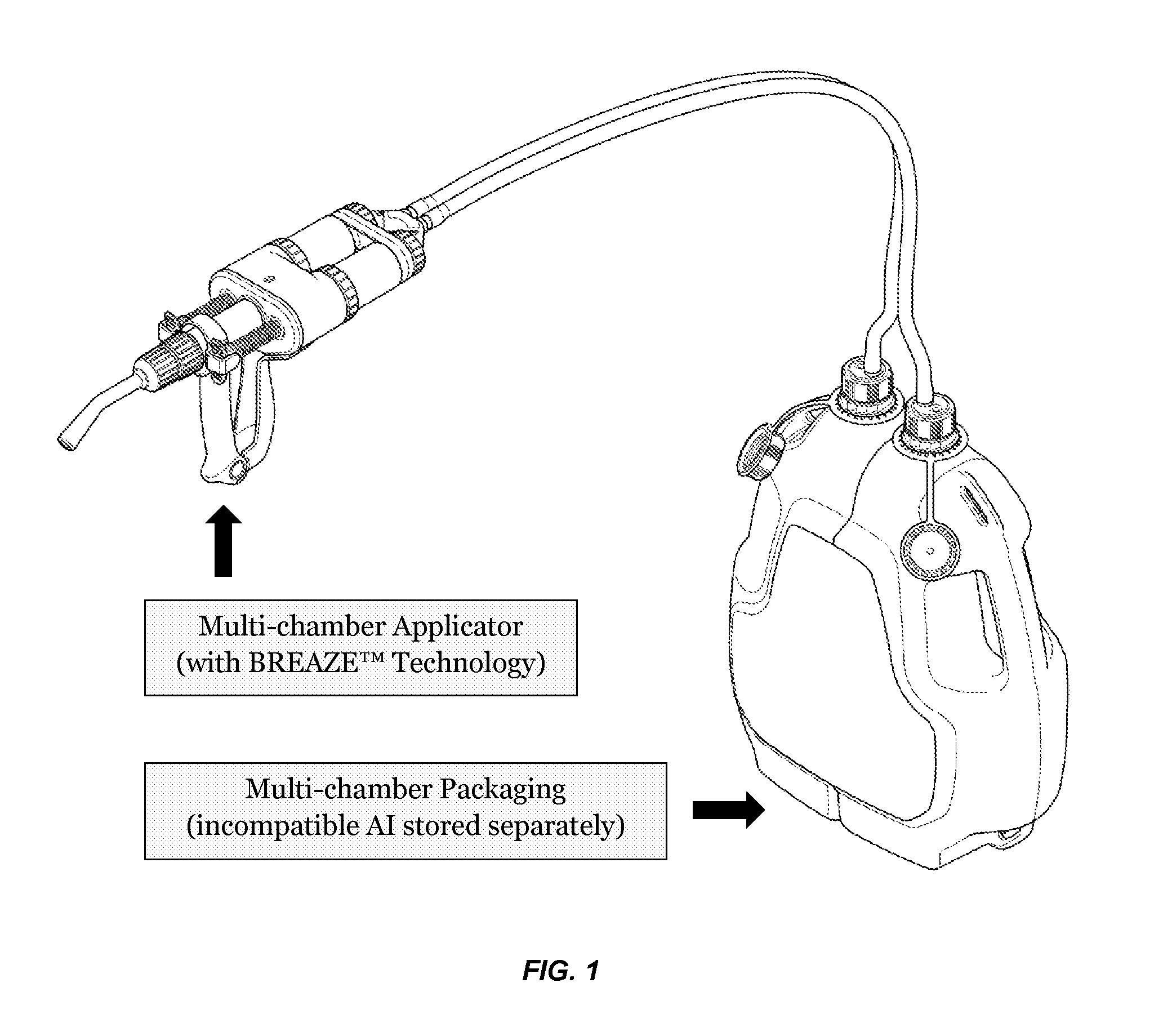
The invention is a multi-chamber, multi-formulation fluid delivery system that includes a multi-chamber applicator for animals. The applicator has reduced squeeze-strength requirements and is suitable for dispensing fluids, including medicaments, to animals. The multi-chamber packaging provides separate storage for formulations containing incompatible active ingredients. The simultaneous delivery methods offer a solution for delivering multiple active ingredients that are not compatible for co-formulation and can provide both a financial advantage and an improved clinical effect. The simultaneous formulation delivery is less stressful to the animals than separate / sequential formulation delivery.

Problems solved by technology

For example, it is well-known that Macrocyclic lactone parasiticides are particularly sensitive to acid hydrolysis, so combining them with water-soluble anthelmintics (e.g. levamisole) has been extremely difficult.
In fact, co-formulation of some active ingredients has proved so challenging that many parasiticide / pesticide manufacturers have opted to supply incompatible compounds as separate formulations / product offerings, even though simultaneous delivery is highly desired by customers.

Method used


Image

  • Multi-chamber, Multi-formulation Fluid Delivery System
  • Multi-chamber, Multi-formulation Fluid Delivery System
  • Multi-chamber, Multi-formulation Fluid Delivery System

Examples


example 1

[0157]In an embodiment, the applicator comprises the parts as shown in FIG. 3B, and as recited in Table 1 below.

TABLE 1Constituent components of the Applicator (200) depicted in FIG. 3B.The numbering of the components applies only to this embodiment(i.e. applicator 200), unless otherwise expressly stated.FIG. 3ANumberQuantityDescription11Delivery Tube Connector22O-Ring32Inlet Nut42BREAZE ™ Inlet Assembly52O-Ring62Barrel Nut74O-Ring82Barrel92O-Ring102Felt Washer112Plunger122Volume Control132Toothed Wheel142Plunger Spring152Plunger Latch161Outlet Manifold (Rear Half)171Outlet Manifold (Front Half)182Outlet Tube191Rear Handle201Dose Display Belt211Outlet Support221Cover231Front Handle241Female Pivot Pin251Male Pivot Pin261Dose Adjuster271Outlet Adapter286Screw291Outlet Tube Connector302Gasket311Nozzle Nut321Dual Chamber Nozzle331Outlet Valve Seat342Outlet Valve351Nozzle Tip

[0158]Accordingly, an applicator according to the disclosure may comprise the following: Delivery Tube Connector (...

example 2

[0161]In an embodiment, the applicator (203) comprises the parts as shown in FIG. 15A-D, and as recited in Table 2 below. The numbering of the components applies only to this embodiment (i.e. applicator 203), unless otherwise expressly stated.

TABLE 2Constituent components of the Applicator (203) depicted, for example, in FIGS. 14A-C and 15A-D.FIG.15A-DPart NameDescription1Front handleSqueeze to discharge.2PlungerNormally the pin is engaged with the vertical slot near the front of theengagementcorresponding plunger shaft (29, 30). Pulling the knob out disengages thatpinplunger for one squeeze. This allows the opposite side to be primed further3Springwithout discharging fluid unnecessarily from the disengaged side. The spring4Knob(3) causes the pin to automatically re-engage the plunger shaft when the fronthandle (1) returns to its forward position.5Rear handleThis is the “fixed handle”for the applicator. In practice, both the front andrear handles move towards one another when the ha...

example 3

Anti-Counterfeiting Measures

[0165]In an embodiment, the red part (shown as dark grey in FIG. 23A-B) snaps onto the bottle at the filling plant and cannot be easily removed. The long dip tube (semi-rigid) may be supplied separately. If the user wishes to use the bottle inverted, then the dip tube is not used. For use with the bottle in the upright position, the user pushes the dip tube in through the hole in the red (dark grey in FIG. 23A-B) cap, until it's in the position shown in the pictures. It is not necessary to remove the red cap. The dip tube cannot be removed once it has been fitted. The red (dark grey) cap includes a one-way air breather valve. This admits air to the bottle when the fluid is withdrawn. The valve prevents fluid leaking out the vent if the bottle is used inverted.

[0166]By preventing air from flowing out from the vent, the valve also makes it more difficult to refill the bottle by pouring liquid in through the fluid outlet. This is particularly true if the dip...


PUM


Abstract

The application discloses a multi-chamber, multi-formulation fluid delivery system, comprising a multi-chamber applicator in fluid communication with multi-chamber packaging. Applicators according to the instant disclosure have reduced squeeze-strength requirements, and are useful for dispensing fluids, including medicaments, to animals, including livestock animals. The multi-chamber packaging provides separate storage for formulations containing incompatible active ingredients, and is suitable for use with the multi-chamber applicator. The application also discloses methods for using the system to simultaneously deliver multiple active ingredients, at least some of which are not suitable for co-formulation, thus reducing the time, economic burden and animal stress involved with applying multiple, separate formulations to animals.

Description

INCORPORATION BY REFERENCE[0001]This application claims priority to US provisional application No. 61 / 878,860, filed on Sep. 17, 2013, and herein incorporated by reference in its entirety. All other references cited herein are likewise incorporated by reference herein in their entirety.FIELD OF THE INVENTION[0002]The present invention relates to multi-chamber fluid delivery systems comprising applicators, connecting means, and multi-chamber packaging. In particular, the invention relates to systems useful in delivering liquid formulations, including medicaments and parasiticides, to animals in need thereof.BACKGROUND OF THE INVENTION[0003]Animal remedies for sheep, cattle and other livestock / production animals are applied by a number of methods including topical or “pour-on” application, oral “drench” application, injection and nasal infusion. Each of these administration routes is typically dispensed from a “pistol grip” style dispensing means. Such an applicator is described in th...

Claims


Application Information

Patent Timeline
Patent Type & Authority Applications(United States)
IPC IPC(8): A01K13/00B05C17/01B05C17/005
CPCA01K13/003B05C17/01B05C17/00576A61D7/00A61M5/19A61M5/2066A61M5/3007A61M5/3148A61M2005/2026A61M2005/3103A61M2005/3115A61M2005/3128A61M2250/00
Inventor PRESCOTT, TODD LUEPKEWALKER, RODNEY GORDONLAUCHLAN, GARETH NIGELTROW, DAVID ANDREW
Owner MERIAL INC
Learn More