Printer with feedback correction of image displacements

Inactive Publication Date: 2015-04-30
EASTMAN KODAK CO
View PDF2 Cites 9 Cited by
  • Summary
  • Abstract
  • Description
  • Claims
  • Application Information

AI Technical Summary

Benefits of technology

This patent describes a method for aligning images that reduces errors between the printed image and the original image. The method does not require special marks on the image and can adjust the image in real-time to compensate for distortions in the receiver medium. The method also takes into account non-uniform distortions in the receiver medium by adjusting the image displacement and spatial adjustments based on location within the image.

Problems solved by technology

For example, the receiver medium could pass through a dryer (in case of printing with liquid inks) or a fusing step (in case of dry powder electrophotography) between the printing of the various channels, which can cause the receiver medium to shrink before the printing of a subsequent channel.
The desired registration of one channel to another can be adversely affected by the dimensional changes of the receiver medium between the printing of the multiple channels.
In such systems, the desired registration of one image plane to another can be adversely affected by the dimensional changes of the receiver medium between the printing of the multiple layers.
Various modes of averaging are described to display a trend in color errors so that the operator is enabled to take corrective action before the color error is too large and the print production yields unacceptable poor print quality.
In general, such printed registration marks are not desirable within the printed image, or anywhere within the finished product; therefore, they can only be placed outside the printed image in a portion of the receiver medium to be trimmed off in a finishing operation.
The need for the trimming operations represents an extra step in the finishing operation, which has the disadvantage of wasting materials and adding cost.

Method used


Image

  • Printer with feedback correction of image displacements
  • Printer with feedback correction of image displacements
  • Printer with feedback correction of image displacements

Examples


Embodiment Construction

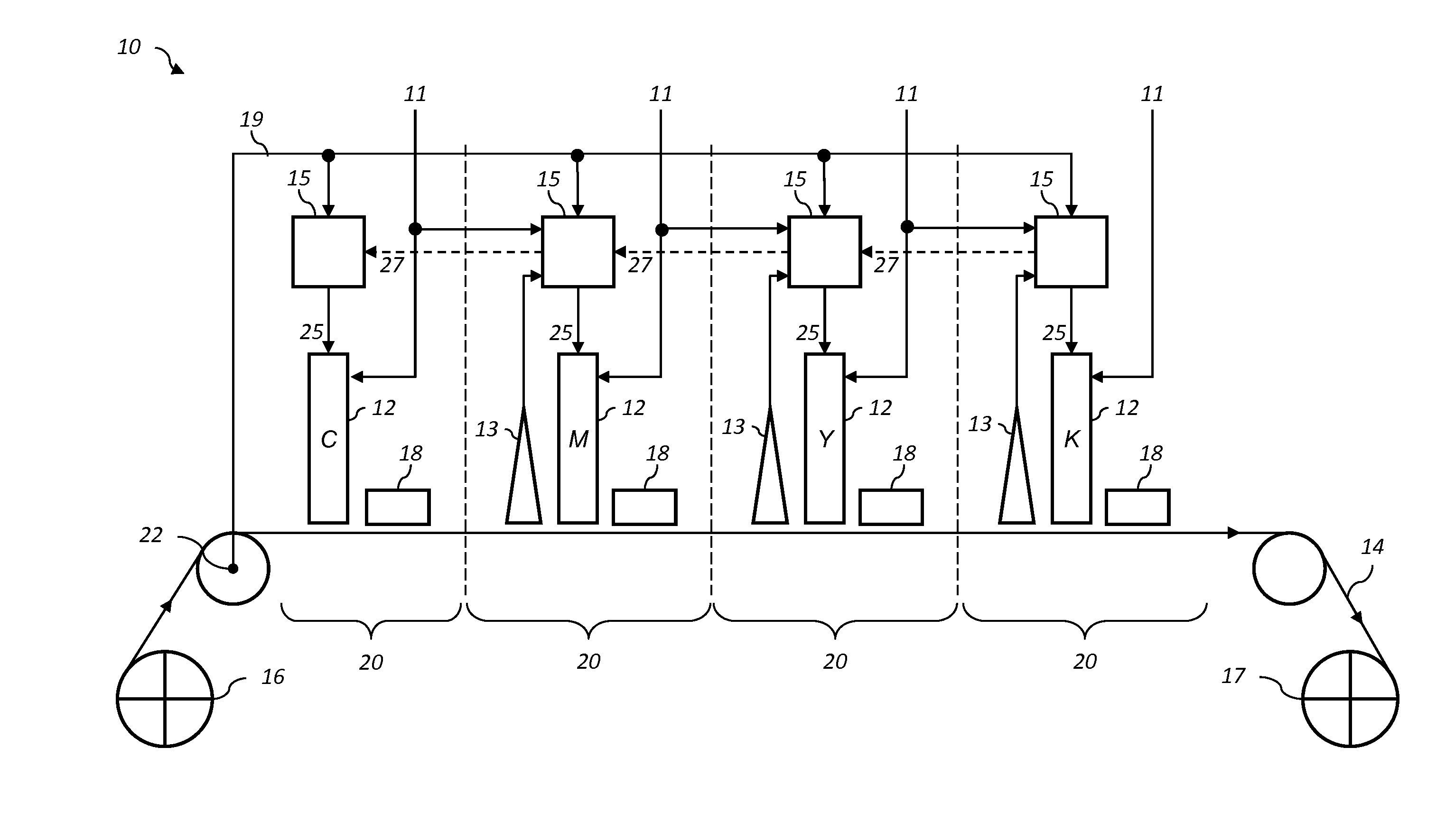
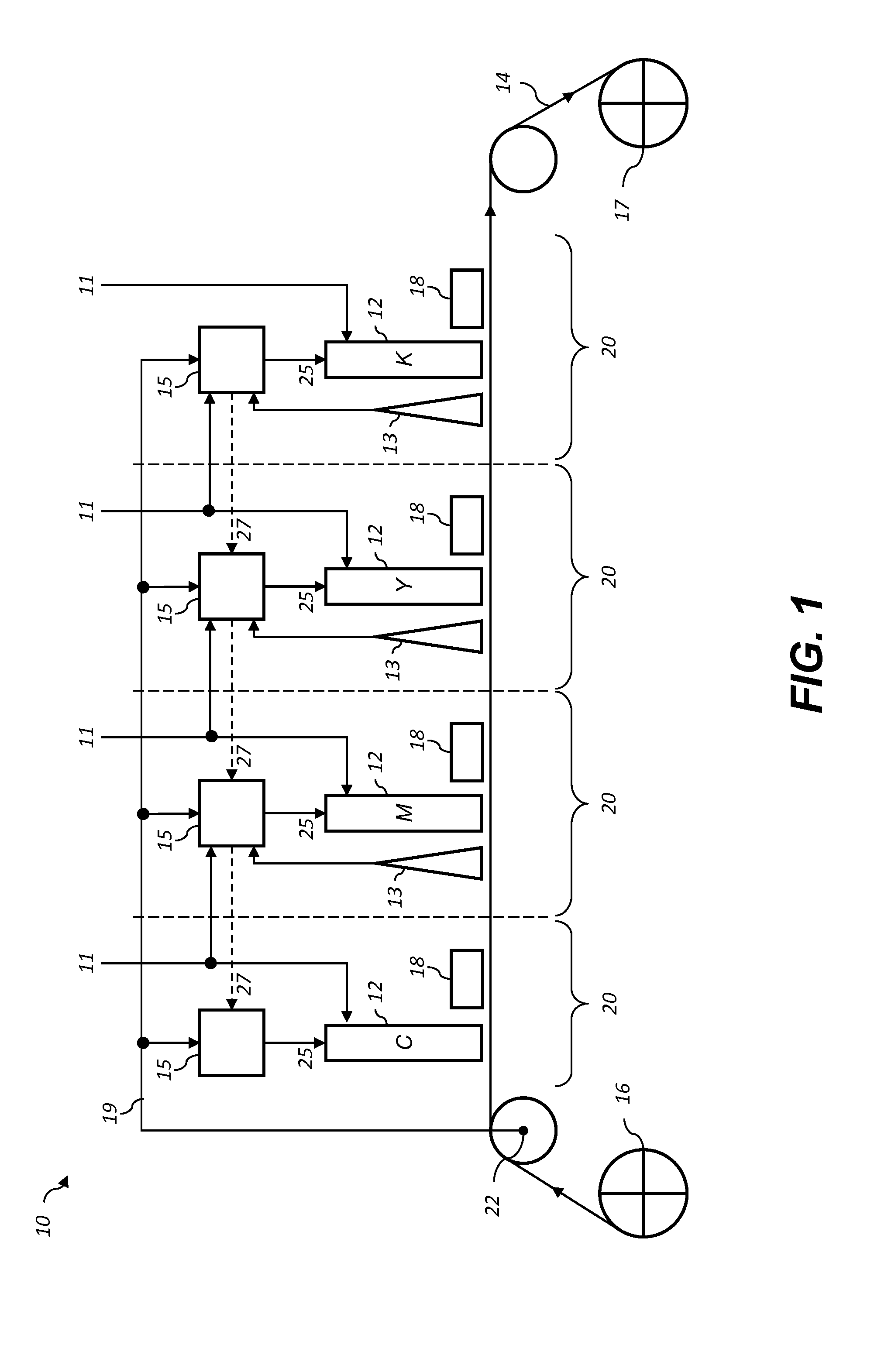
[0040]The present description will be directed in particular to elements forming part of, or cooperating more directly with, apparatus in accordance with the present invention. It is to be understood that elements not specifically shown or described may take various forms well known to those skilled in the art.

[0041]In the following description, some aspects of the present invention will be described in terms that would ordinarily be implemented as software programs. Those skilled in the art will readily recognize that the equivalent of such software may also be constructed in hardware. Because image processing algorithms and systems are well known, the present description will be directed in particular to algorithms and systems forming part of, or cooperating more directly with, the method in accordance with the present invention. Other aspects of such algorithms and systems, together with hardware and software for producing and otherwise processing the image signals involved there...


PUM


Abstract

A printer includes a marking unit for printing an image plane on a receiver medium. A digital image capture system is positioned downstream of the marking unit, and is used to capture an image of a printed image plane. Image data for the image plane is compared to the captured image to determine a displacement between a nominal location and an actual location of the printed image data. Corresponding spatial adjustments are applied to image data for a subsequent image to reduce alignment errors between the nominal and actual locations of the printed image data in the subsequent image.

Description

CROSS-REFERENCE TO RELATED APPLICATIONS[0001]Reference is made to commonly assigned, co-pending U.S. patent application Ser. No. __ / ______ (Docket K001275), entitled: “Printer with image plane alignment correction”, by Howard et al.; and to commonly assigned, co-pending U.S. patent application Ser. No. __ / ______ (Docket K001642), entitled: “Printer with feedback correction of image plane alignment”, by Howard et al., each of which is incorporated herein by reference.FIELD OF THE INVENTION[0002]This invention generally relates to a digital printing system, and more particularly to the correction of image plane displacement errors based on image comparisons made between the image data and a captured image of the printed output.BACKGROUND OF THE INVENTION[0003]In multi-channel digital printing systems, images for a plurality of image channels are printed in alignment onto a receiver medium. In many such digital printing systems, a plurality of printing modules (e.g., inkjet printheads ...

Claims


Application Information

Patent Timeline
IPC IPC(8): G06K15/02G06K9/62G06K9/20
CPCG06K15/027G06K9/6201G06K9/20G06K15/1872B41J2/2135B41J2/2146G06T7/001G06T2207/10016G06T2207/30144G06F18/22
Inventor HOWARD, JOSHUA HARTREGELSBERGER, MATTHIAS HERMANNSPAULDING, KEVIN EDWARD
Owner EASTMAN KODAK CO
Why Eureka
Try Eureka