
Wireless inductive charging of weapon system energy source

a technology of inductive charging and energy source, applied in the field of electric devices, can solve the problems of affecting the ability of soldiers to effectively use their weapons, and achieve the effect of reducing the damage of the soldier

Active Publication Date: 2015-04-30
CYNETIC DESIGNS
View PDF5 Cites 40 Cited by
  • Summary
  • Abstract
  • Description
  • Claims
  • Application Information

AI Technical Summary

Benefits of technology

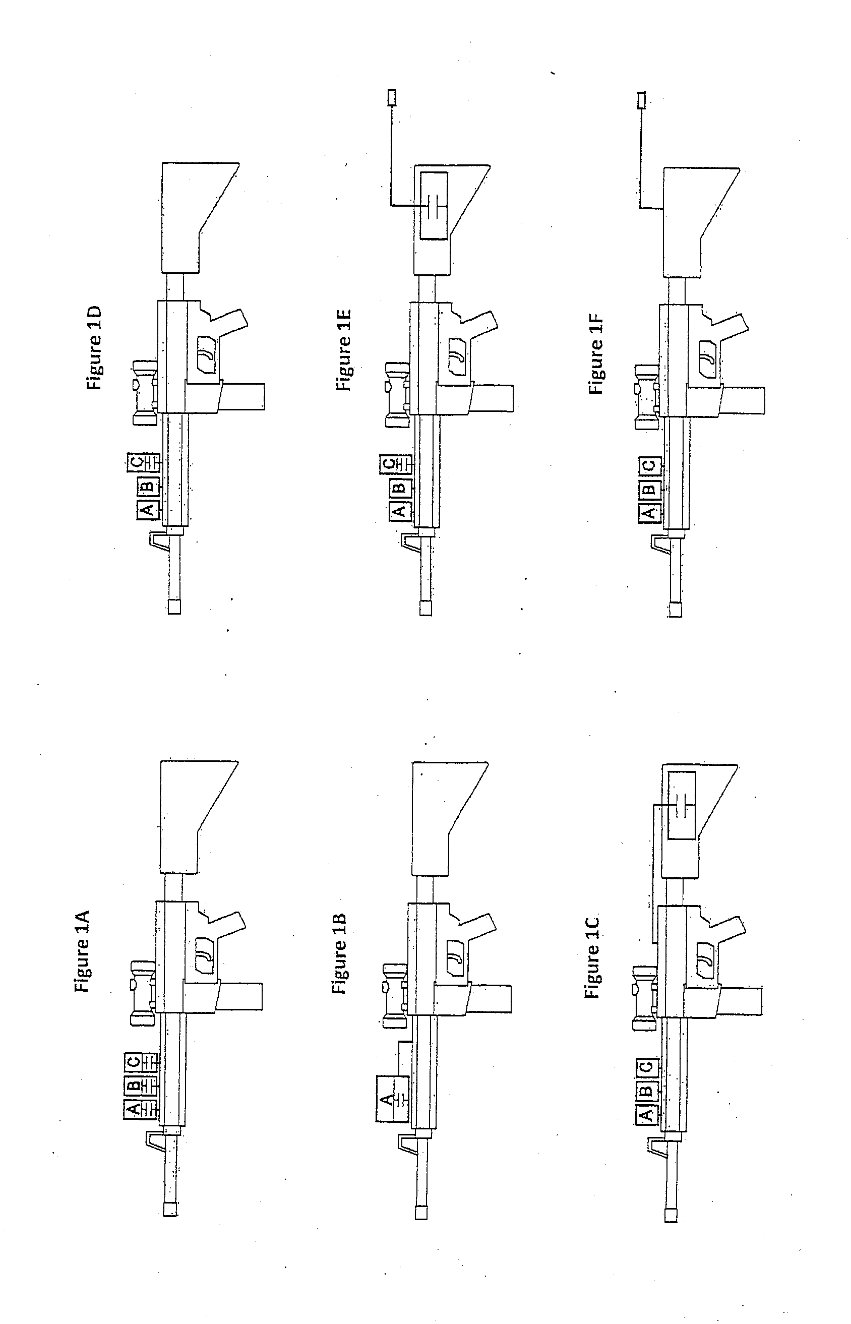
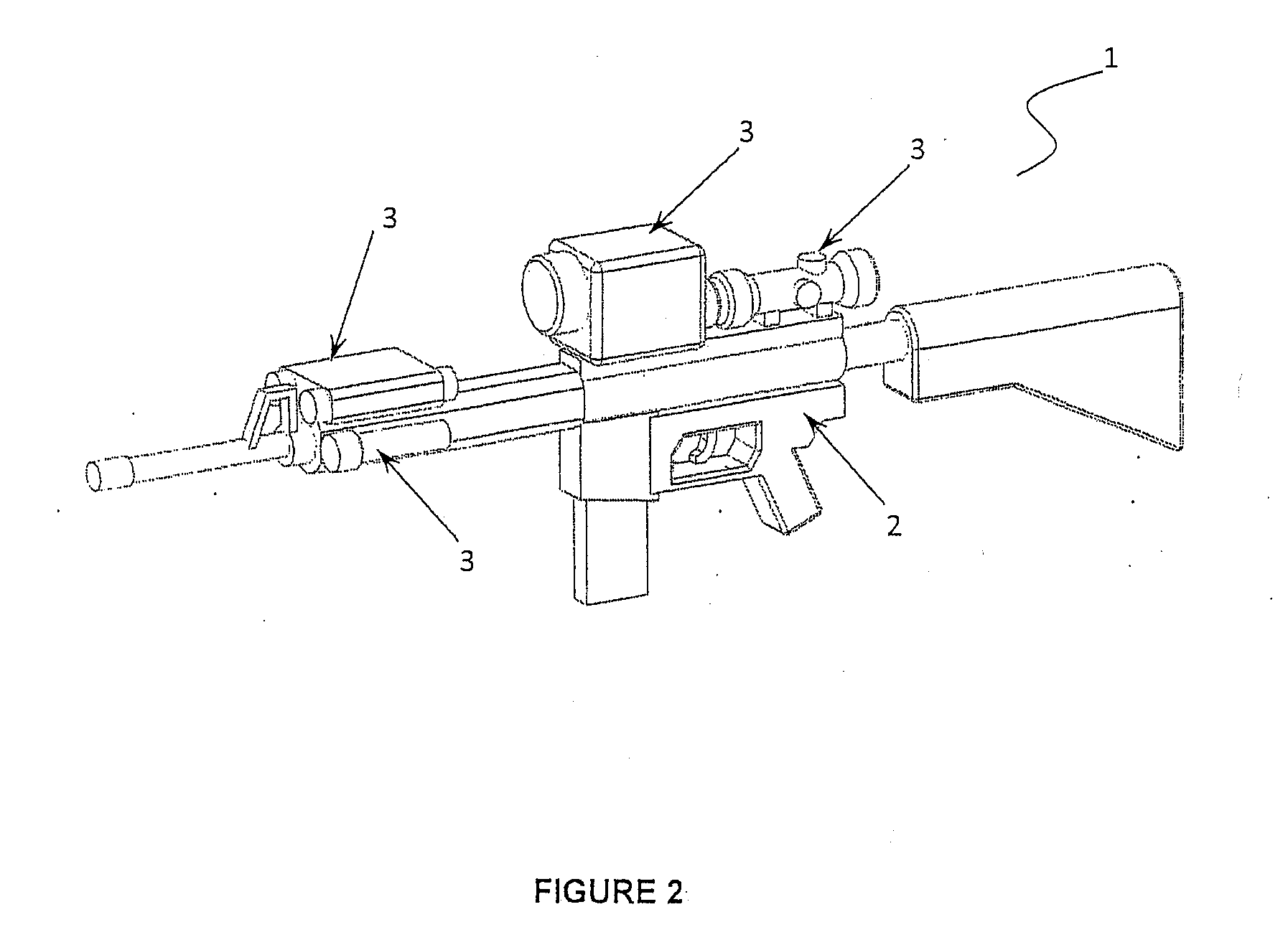
The present invention is a charging system for a weapon system that uses wireless inductive charging. The charging system includes a charging portion in the weapon system and a charging base. The charging portion has a first inductive coil that is connected to the weapon system platform's electrical power supply. The charging base has a second inductive coil that is mated with the charging portion to provide charging power. The charging system is designed to provide fast and efficient charging for the weapon system. The charging system can be used in various weapon systems such as a weapon system platform, a motorized vehicle, an aircraft, a water-bourne craft, a water-submersible craft, a spacecraft, or a forward-operating base. The charging system can also be used in a weapon system that has a stock and the charging portion is the stock of the weapon.

Problems solved by technology

The first is that it has become apparent that the center of gravity due to the weight of the accessory devices and their batteries has created a detrimental effect on the human factors or ergonomics of the weapon and consequently on the ability of the soldier to use his weapon effectively.
These type of weapons may utilise rechargeable central power sources that require considerable amounts of rapid power transfer.

Method used


Image

  • Wireless inductive charging of weapon system energy source
  • Wireless inductive charging of weapon system energy source
  • Wireless inductive charging of weapon system energy source

Examples


Embodiment Construction

[0057]This application incorporates by reference US patent “Contactless Battery Charging Apparel”, which issued to Soar as U.S. Pat. No. 7,994,752 B2 wherein Soar describes the inductive charging of a weapon from the soldiers torso garment. Soar's patent describes the opportunistic, low power charging of a weapons integrated central battery by the provision of wireless inductive power from the torso garment of a soldier to the weapon.

[0058]The invention described herein, in one aspect, provides high rates of wireless inductive power transfer to allow the fast charging of a weapon's central battery when a soldier is in or on one of the aforesaid platforms, for example when seated in a vehicle, aircraft or at a FOB. Published patent applications by Soar are incorporated herein by reference, for example in one of his published patent applications entitled Vehicle Seat Inductive Charger and Data Transmitter, US Patent Application publication no. US2013 / 0005251 A1, published Jan. 3, 2013...


PUM


Abstract

A charging system for the wireless inductive charging of an energy source in a weapon in a weapon system. The charging system includes a first portion of the weapon system, wherein the first portion has a first inductive coil therein, and a female receiver sized for receiving, in a male-female mating engagement, the first portion of the weapon system. The receiver has a second inductive coil positioned to inductively couple with the first inductive coil when the first portion of the weapon system is in the male-female mating engagement with the receiver. The first inductive coil is adapted for electrical connection to a weapon system platform electrical power supply and has a direct current resistance of less than or equal to substantially 0.2 Ohms so as to be adapted to provide charging power having a peak power of at least substantially 10 watts.

Description

CROSS REFERENCE TO RELATED APPLICATIONS[0001]This application is a continuation-in-part from U.S. patent application Ser. No. 13 / 502,045 entitled Inductively Coupled Power and Data Transmission System which is a national phase entry of PCT application no. PCT / CA2010 / 001638, which claims priority from U.S. provisional application Ser. No. 61 / 272,621 and is a continuation-in-part from U.S. application Ser. No. 11 / 922,788 now U.S. Pat. No. 7,863,859, and U.S. application Ser. No. 12 / 926,858, now U.S. Pat. No. 7,994,752, both entitled Contactless Battery Charging Apparel, and U.S. application Ser. Nos. 12 / 923,594 and 13 / 533,832 both entitled Vehicle Seat Inductive Charger and Data Transmission System. This application also claims priority from U.S. provisional application No. 61 / 809,017 entitled Wireless Inductive Charging of a Weapon System Battery.FIELD OF THE INVENTION[0002]This invention relates to the field of electrical devices which are charged or otherwise powered by inductive c...

Claims


Application Information

Patent Timeline
IPC IPC(8): H02J7/02F41A35/00H02J7/00
CPCH02J7/025F41A35/00H02J7/0042F41G11/00F41A23/18F41C23/22H02J50/10H02J7/00036H02J7/00047H02J50/70H02J50/12
Inventor SOAR, ROGER J.
Owner CYNETIC DESIGNS
Learn More