Devices and Systems for Improved Traffic Control Signal Assembly

Inactive Publication Date: 2015-04-30
TOWNSEND JR ROBERT E
View PDF3 Cites 3 Cited by
  • Summary
  • Abstract
  • Description
  • Claims
  • Application Information

AI Technical Summary

Benefits of technology

The patent text describes a new way to make traffic control signals that are stronger and more durable. The approach is called a continuous load path hanger, which is separate from the housing of the electronics. This hanger provides a continuous path for the load to flow through, making the signal more resistant to damage. The invention also integrates the housing of the electronics and indicator housing, which saves space and allows for the use of stronger materials. This allows for easier installation and maintenance of the traffic control signals.

Problems solved by technology

Traffic signal hangers and housings have a known history of structural failures during hurricanes which sometimes result in injury and even fatalities due to uncontrolled roadway intersections.
Traffic control signals, when designed as individual components, are very susceptible to damage from hurricane force winds, and multiple points of failure can occur in more than one specific component.
Prior art devices suffer from flawed design in which the housing of the electronics, known as the “disconnect box” and / or “disconnect hanger,” itself is used to support traffic signals by multiple linear load paths around the periphery of the disconnect box, rendering it susceptible to structural failures, especially at the disconnect box's cantilevered shelf areas during high wind events.

Method used


Image

  • Devices and Systems for Improved Traffic Control Signal Assembly
  • Devices and Systems for Improved Traffic Control Signal Assembly
  • Devices and Systems for Improved Traffic Control Signal Assembly

Examples


example 1

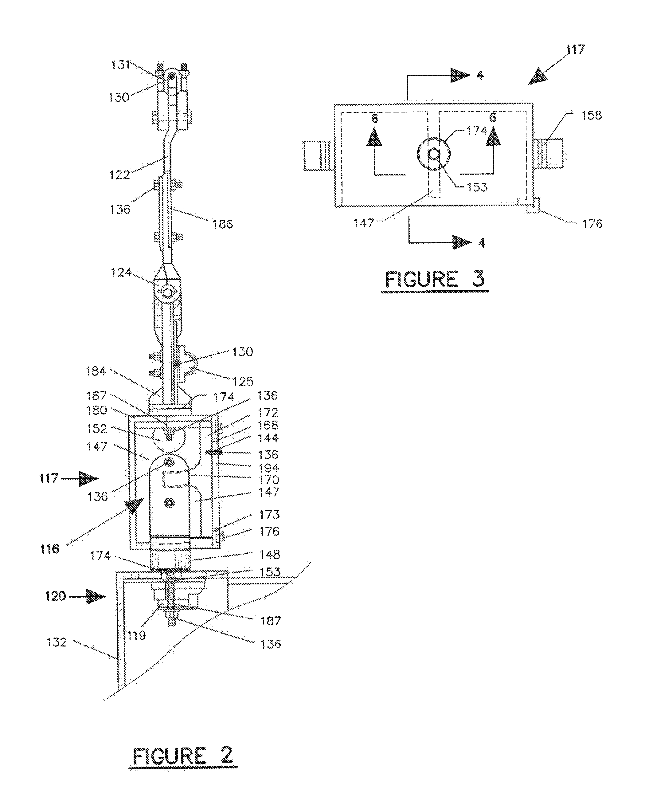
[0182]Referring now to the drawings, according to a first embodiment of the invention (FIG. 1-FIG. 7), FIG. 1 illustrates an interior frontal view of a traffic control signal with the door removed for clarity. The traffic control device 120 comprises a span wire saddle clamp 131 connected to the existing span wire 130 and an existing hanger 122 with clevis pin 189. In another embodiment of the invention, the structural extension can be connected to the upper connection device 186 that is pivotally connected with pivotal connection 124. The pivot pin 188 pivots about an axis parallel to the above and below existing span wires 130. In one embodiment, multiple pivots with multiple planes can be achieved provided vertical movement is restricted.

[0183]Although the traffic control device can accept common single and dual span (upper and lower) wire hangers such as a “tether cable”, rigid flat aluminum, and even pipe hangers, in an embodiment of the invention, the hanger is the pivotal ass...

example 2

[0192]FIG. 8 illustrates a slight modification of the embodiment described above and depicted in FIGS. 1-7. In this embodiment the integral support flange 147a is supporting the removable hub 148a integral ascending vertical support 129a using the removable hub's integral transverse support bar 146a to carry the primary loads along with the associate support flange 166, which is secured by bolting the support flange 166 to the housing using fasteners 136 through each of the fastener apertures 153. The housing's roof 180a and floor 178a are depicted for ease of reference.

example 3

[0193]Another embodiment of the invention is depicted in FIGS. 9-12, wherein the traffic control signal includes a continuous central load path traffic signal hanger and a removable terminal housing supported by the continuous load path traffic signal hanger.

[0194]FIG. 9 depicts the primary components of an embodiment of the present invention including a continuous central load path hanger 216 and removable terminal housing 215. Sometimes a signal reinforcement 219 can be included. This embodiment of the invention can be provided without a removable hub. The terminal housing can provide a weatherproof housing for electrical components of traffic control devices.

[0195]In this embodiment of the invention, a dual span wire system is depicted with the existing upper span wire 230 used to support the gravitational load of the traffic control device 220. The saddle clamp 231 is fastened to the span wire 230 by utilizing the appropriate fasteners 236. The hanger / extension 222 is secured to...


PUM

PropertyMeasurementUnit
Fractionaaaaaaaaaa
Tensionaaaaaaaaaa

Abstract

Methods and apparatuses are provided for improved traffic control devices including a continuous central hanger support system that is integral to the traffic control device and provides a central load path. In an embodiment of the invention, the terminal housing and traffic signal housing of the traffic control device can be included in a single unit housing. A single unit housing can also include an integral backplate. Also provided are span wire clamps, tether clamps, and mast arm clamps that can be used to affix the continuous central hanger of the traffic control device to various fixtures such as a single span wire, two span wires, a pole or a mast arm. The continuous central hanger integrated with the single unit housing can provide the traffic control device with improved securement of electrical components and structural stability for survivability during high wind events as compared to conventional traffic signal devices.

Description

CROSS-REFERENCE TO RELATED APPLICATIONS[0001]This application is a continuation-in-part of U.S. application Ser. No. 13 / 839,666, filed Mar. 15, 2013 which is a continuation-in-part of U.S. application Ser. No. 13 / 554,475, filed on Jul. 20, 2012, U.S. Pat. No. 8,540,392, which claims the benefit under 35 U.S.C. §119 of U.S. Patent Application Nos. 61 / 627,739, filed Oct. 16, 2011; 61 / 628,103, filed Oct. 23, 2011; 61 / 628,439, filed Oct. 30, 2011; 61 / 628,440, filed Oct. 30, 2011; 61 / 628,827, filed Nov. 7, 2011; 61 / 629,744, filed Nov. 26, 2011; 61 / 631,555, filed Jan. 6, 2012; 61 / 632,177, filed Jan. 19, 2012, and 61 / 685,862, filed Mar. 26, 2012, U.S. application Ser. No. 13 / 839,666 claims the benefit under 35 U.S.C. §119 of U.S. Patent Application Nos. 61 / 689,082, filed May 29, 2012, 61 / 690,861, filed Jul. 6, 2012, and the current application claims the benefit under 35 U.S.C. §119 of U.S. Patent Application No. 61 / 922,826, filed Jan. 1, 2014, all of which are hereby incorporated by refer...

Claims


Application Information

Patent Timeline
IPC IPC(8): F21V21/008F16M13/02G08G1/095
CPCF21V21/008F16M13/02G08G1/095Y10T29/49826
Inventor TOWNSEND, JR., ROBERT E.
Owner TOWNSEND JR ROBERT E
Why Eureka
Try Eureka