Internal combustion engine control apparatus
- Summary
- Abstract
- Description
- Claims
- Application Information
AI Technical Summary
Benefits of technology
Problems solved by technology
Method used
Image
Examples
embodiment 1
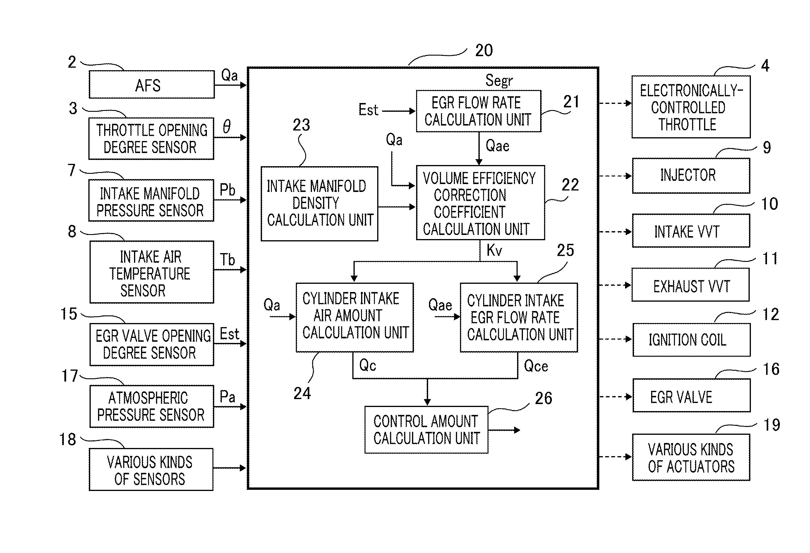
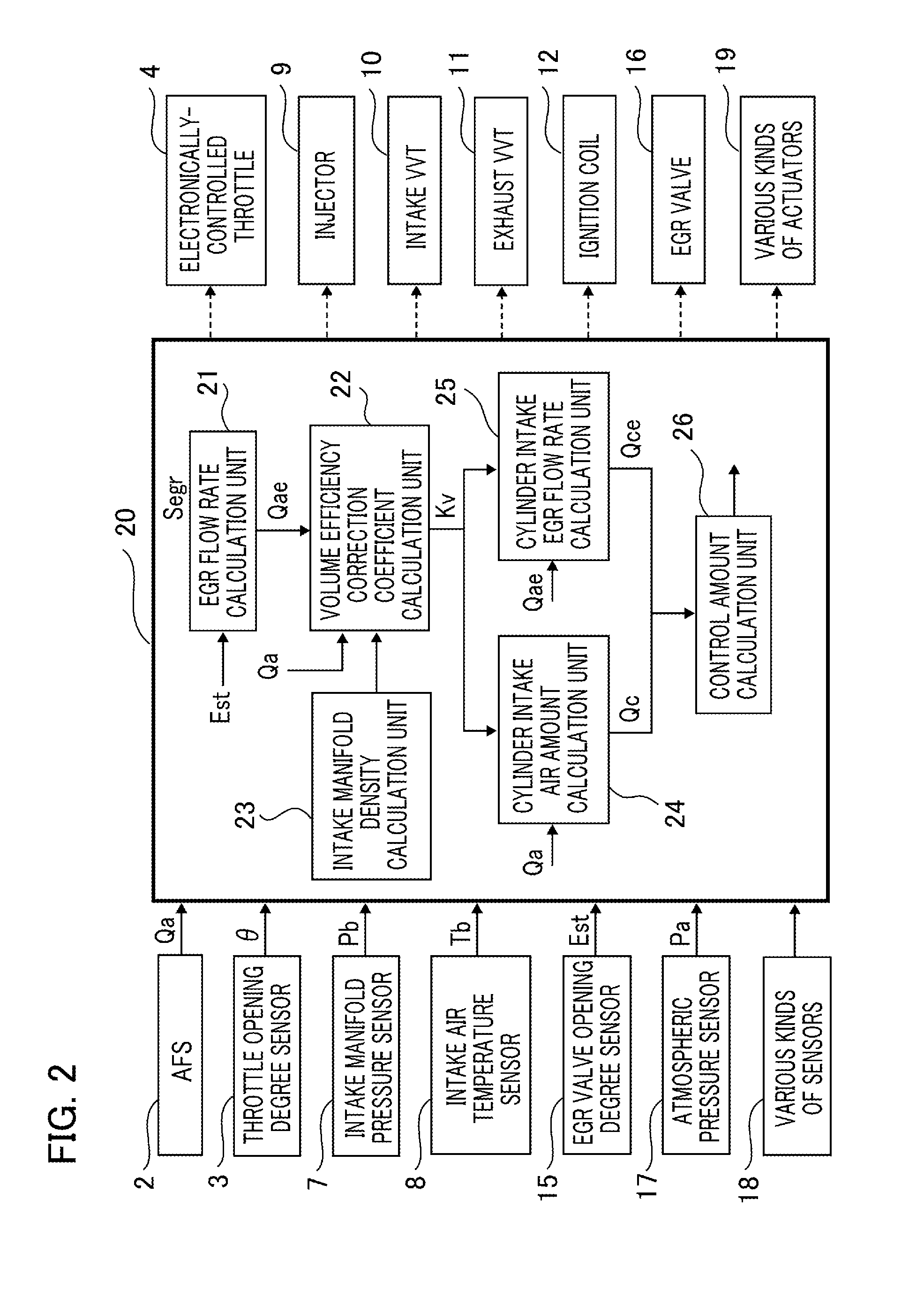
[0021]Hereinafter, an internal combustion engine control apparatus according to Embodiment 1 of the present invention will be explained in detail with reference to the drawings. FIG. 1 is a configuration diagram schematically illustrating an internal combustion engine to which the internal combustion engine control apparatus according to Embodiment 1 of the present invention is applied. In FIG. 1, an air flow sensor (referred to as an AFS, hereinafter) 2 that measures an intake air amount is provided at the upstream side of the intake system of an internal combustion engine 1. At the downstream side of the AFS 2, an electronically-controlled throttle 4 that can electrically be controlled to adjust the intake air amount is provided. In order to measure the opening degree of the electronically-controlled throttle valve 4, a throttle opening degree sensor 3 is provided. It may be allowed that instead of the AFS 2, another unit is utilized that measures an intake air amount, for example...
PUM
 Abstract
Description
Claims
Application Information
 - R&D
- Intellectual Property
- Life Sciences
- Materials
- Tech Scout
- Unparalleled Data Quality
- Higher Quality Content
- 60% Fewer Hallucinations
Browse by: Latest US Patents, China's latest patents, Technical Efficacy Thesaurus, Application Domain, Technology Topic, Popular Technical Reports.
© 2025 PatSnap. All rights reserved.Legal|Privacy policy|Modern Slavery Act Transparency Statement|Sitemap|About US| Contact US: help@patsnap.com


