Decoding method, decoding circuit, memory storage device and controlling circuit unit
a decoding circuit and memory storage device technology, applied in the field of decoding methods, can solve the problems of limited correction capability and increase decoding latency, and achieve the effect of reducing decoding latency
- Summary
- Abstract
- Description
- Claims
- Application Information
AI Technical Summary
Benefits of technology
Problems solved by technology
Method used
Image
Examples
first exemplary embodiment
[0037]Generally, a memory storage device (also known as a memory storage system) includes a rewritable non-volatile memory module and a controller (also known as a control circuit). The memory storage device is usually configured together with a host system so that the host system may write data to or read data from the memory storage device.
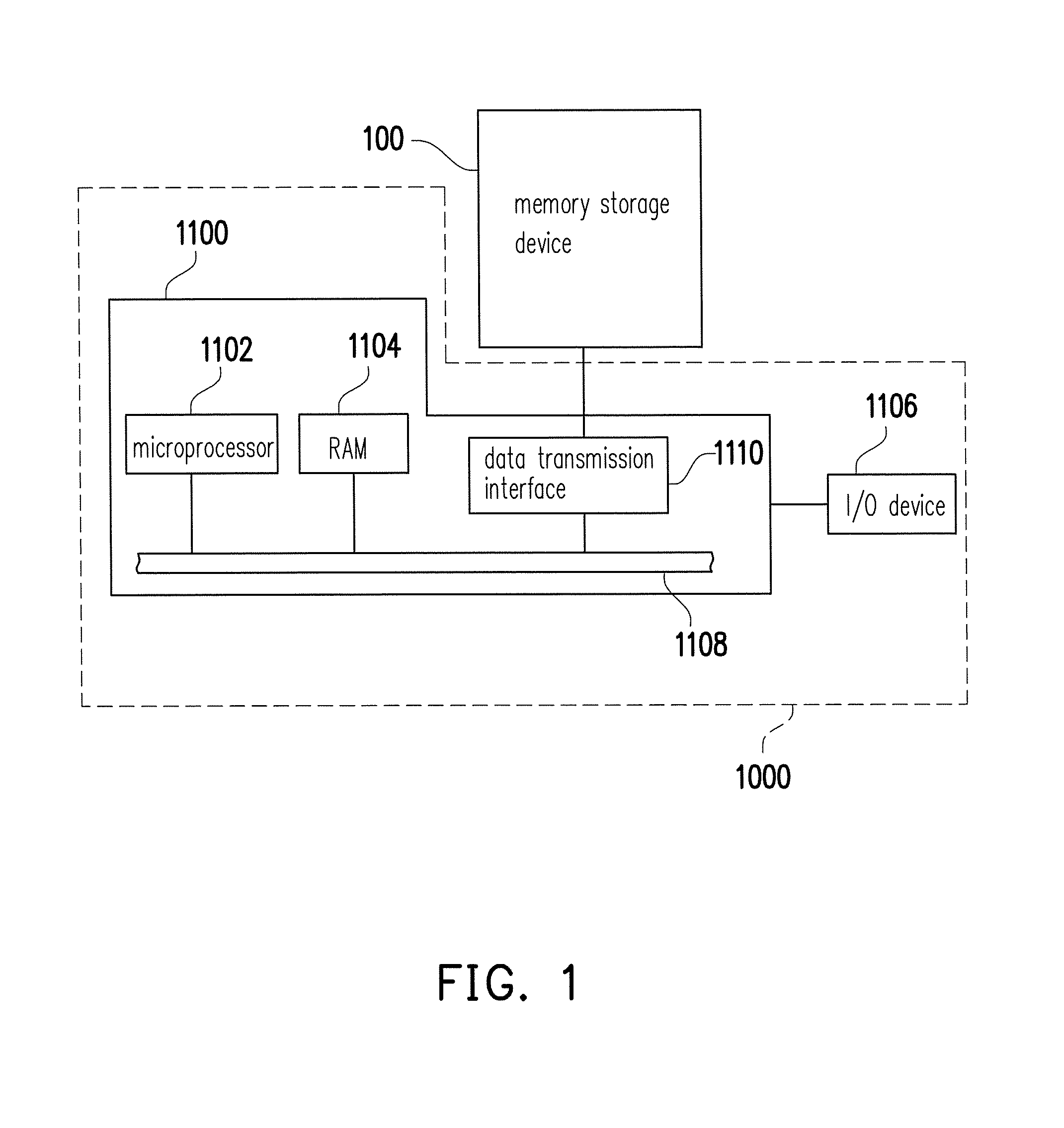
[0038]FIG. 1 illustrates a host system and a memory storage device according to an exemplary embodiment. FIG. 2 is a schematic diagram illustrating a computer, an input / output device and a memory storage device according to an exemplary embodiment.
[0039]Referring to FIG. 1, a host system 1000 includes a computer 1100 and an input / output (I / O) device 1106. The computer 1100 includes a microprocessor 1102, a random access memory (RAM) 1104, a system bus 1108, and a data transmission interface 1110. For example, the I / O device 1106 includes a mouse 1202, a keyboard 1204, a display 1206 and a printer 1208 as shown in FIG. 2. It should be understood ...
second exemplary embodiment
[0076]In second exemplary embodiment, when the memory management circuit 202 reads the data bits from rewritable non-volatile memory module 106, a plurality of read voltages are used to obtain a plurality of verification bits form each of the first memory cells, in which one read voltage is corresponding to one of the verification bits. The verification bits may be used to decide the data bit, or may be used to obtain a channel reliability message. The iterative decoding preformed in case each of the memory cells includes multiple verification bits is referred to as a soft bit mode decoding.
[0077]FIG. 13 illustrates a schematic diagram of reading a verification bit according to an exemplary embodiment. Referring to FIG. 13, it is assumed that the memory cell in a storage status 1510 stores the bit “1”, and the memory cell in a storage status 1520 stores the bit “0”. The storage status 1510 may be partially overlapped with the storage status 1520, namely, under some specific read vol...
third exemplary embodiment
[0090]Hereinafter, only differences between third embodiment and second embodiment are described below. In third exemplary embodiment, the memory management circuit 202 may obtain the verification bit of the memory cell by only using one read voltage. The iterative decoding preformed in this case is referred to as a hard bit mode decoding. Furthermore, in third exemplary embodiment, the number of the channel reliability message is one. More specifically, after reading a verification bit of each of the first memory cells according to a read voltage, the memory management circuit 202 may obtain a log likelihood ratio of each of the first memory cells according to the corresponding verification bit. The memory management circuit 202 may also calculate an average value of the log likelihood ratios of the first memory cells to serve as the channel reliability message, namely, all of the data bits are corresponding to the same channel reliability message.
[0091]In a first iteration of thir...
PUM
 Abstract
Description
Claims
Application Information
 - R&D
- Intellectual Property
- Life Sciences
- Materials
- Tech Scout
- Unparalleled Data Quality
- Higher Quality Content
- 60% Fewer Hallucinations
Browse by: Latest US Patents, China's latest patents, Technical Efficacy Thesaurus, Application Domain, Technology Topic, Popular Technical Reports.
© 2025 PatSnap. All rights reserved.Legal|Privacy policy|Modern Slavery Act Transparency Statement|Sitemap|About US| Contact US: help@patsnap.com


