Arrangement and a method for controlling the temperature of air being fed to a vehicle engine

a technology for vehicle engines and temperature, which is applied in the direction of combustion-air/fuel-air treatment, fuel intakes, vehicles, etc., can solve the problems of increasing the fuel consumption of the engine, requiring a sufficient inflow of air, and not equipped with a turbocharger device, so as to increase the speed of the air fan and increase the temperature of the air. , the effect of increasing the degree of cooling

Active Publication Date: 2015-04-23
VOLVO CONSTR EQUIP
View PDF14 Cites 3 Cited by
  • Summary
  • Abstract
  • Description
  • Claims
  • Application Information

AI Technical Summary

Benefits of technology

[0020]A further advantage of the invention is that it constitutes an energy-efficient solution for controlling air temperature due since it uses waste heat from the engine to increase the temperature of air which is fed into the engine.
[0021]According to an embodiment, the invention constitutes a “self-regulating” solution which provides a boost effect in the sense that when the engine needs colder air, the speed of the air fan is increased (which leads to a higher degree of cooling in the charge air cooler), which at the same increases the inflow into the engine compartment and a larger part of the input air to the engine will be constituted by colder air.
[0022]A further advantage of the invention is that the service interval of the engine's air filter can be extended since the engine air intake can be located inside the engine compartment, which is a relatively clean place on a working machine such as an articulated hauler.
[0023]According to an embodiment of the invention a control unit is arranged to control the air fan for providing said airflow to the engine air intake. Suitably, the air fan is arranged for selectively being operated in a first mode of operation with a relatively high speed for providing an airflow from said ambient air intake to said engine air intake, thereby decreasing the temperature of the air flowing into said engine air intake; or a second mode of operation with a relatively low speed for providing an airflow from within the engine compartment to said engine air intake, thereby increasing the temperature of the air flowing into said engine air intake. In this manner, an efficient control of the air temperature can be obtained which is adapted to various operational conditions of the engine.
[0024]According to an embodiment, the speed of the air fan is controlled depending on the operational condition of said engine. This means that the speed of the air fan can be chosen in order to provide a suitable amount of intake air for each given type of operation of the engine.
[0025]Furthermore, when the engine needs warmer air, the speed of the charge air cooler's fan can be decreased, which at the same time reduces the inflow of air into the engine compartment, and a higher proportion of the intake air to the engine will be constituted by air which has been heated by the engine.

Problems solved by technology

Obviously, combustion engines which are not equipped with a turbocharger device also need a sufficient inflow of air.
Even though the aim of raising the exhaust gas temperature is obtained in is manner, the method leads to a disadvantage since it increases the fuel consumption of the engine.

Method used


Image

  • Arrangement and a method for controlling the temperature of air being fed to a vehicle engine
  • Arrangement and a method for controlling the temperature of air being fed to a vehicle engine
  • Arrangement and a method for controlling the temperature of air being fed to a vehicle engine

Examples


Embodiment Construction

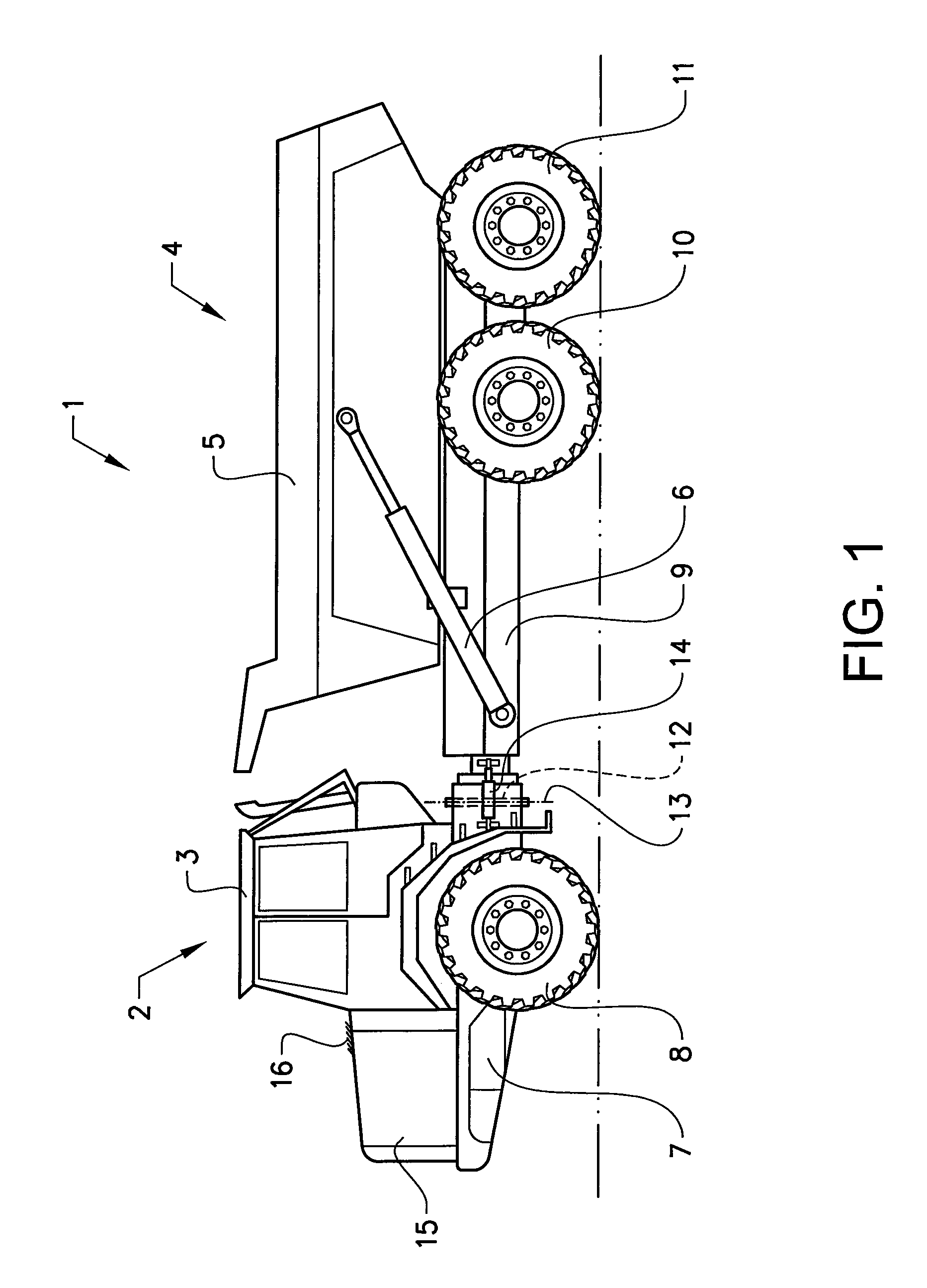
[0032]FIG. 1 is an illustration of a working machine 1 in the form of an articulated hauler having a front section 2 with a cab 3 for a driver and a rear section 4 with a container 5 for receiving a load. The container 5 is preferably pivotally connected to the rear section and tiltable by means of a pair of tilting cylinders 6, for example hydraulic cylinders. The front section has a front frame 7 and a pair of wheels 8 suspended from the front frame 7. The rear section 4 has a rear frame 9 and two pairs of wheels 10, 11 suspended from the rear frame 9.

[0033]The working machine is frame-steered, i.e. there is a pivot point 12 connecting the front section 2 and the rear section 4 of the working machine 1. The front section 2 and the rear section 4 are pivotally connected to each other for pivoting about a substantially vertical pivot axis 13.

[0034]The working machine 1 preferably comprises a hydraulic system having two hydraulic cylinders 14, steering cylinders, arranged on opposite...


PUM


Abstract

An arrangement for controlling the temperature of air being fed to a vehicle engine includes an engine compartment in which the engine is arranged. The engine compartment is provided with an ambient air intake allowing an airflow into the engine compartment. The engine is provided with an engine air intake arranged inside the engine compartment. The arrangement further includes an air fan for forcing the airflow via the ambient air intake into the inside of the engine compartment. The engine air intake is arranged in a position allowing at least a substantial part of the airflow to enter the engine air intake.

Description

BACKGROUND AND SUMMARY[0001]The present invention relates to an arrangement for controlling the temperature of air being fed to a vehicle engine, the arrangement comprising an engine compartment in which said engine is arranged, said engine compartment being provided with an ambient air intake allowing an airflow into said engine compartment, said engine being provided with an engine air intake arranged inside the engine compartment, and an air fan for forcing the airflow via the ambient air intake into the inside of the engine compartment.[0002]The invention also relates to a method for controlling the temperature of air being fed to a vehicle engine arranged in an engine compartment, said engine being provided with an engine air intake arranged inside the engine compartment, said method composing controlling an air fan for forcing an airflow of ambient air into the engine compartment.[0003]The invention is applicable on working machines within the field of industrial construction ...

Claims


Application Information

Patent Timeline
Patent Type & Authority Applications(United States)
IPC IPC(8): F01P7/04F02M35/10F01P5/06
CPCF01P7/04F02M35/10F01P5/06B60K13/02F02M35/10268F02M35/164F02B29/0431F02M35/10013F01P2001/005B60Y2200/415F01P7/048F01P7/12F01P2060/02B60Y2200/142Y02T10/12
Inventor HAEGERSTAM, JOAKIM
Owner VOLVO CONSTR EQUIP
Why Eureka
Try Eureka