Cooling device for internal combustion engine

Inactive Publication Date: 2017-02-02
TOYOTA JIDOSHA KK
View PDF14 Cites 11 Cited by
  • Summary
  • Abstract
  • Description
  • Claims
  • Application Information

AI Technical Summary

Benefits of technology

The present invention relates to a cooling device for an internal combustion engine that controls the opening and closing states of multiple cooling circuits through a control valve. The technical effects of the invention include avoiding boiling of the cooling medium while closing all cooling circuits, controlling the flow of cooling medium to the oil cooler for improved fuel efficiency, and controlling the air temperature for better comfort. The control valve includes a rotor that changes the opening and closing states of the cooling circuits based on its rotation angle, and the invention restricts the output power of the engine and the speed change of the transmission to prevent excessive pressure and heat generation, thereby avoiding boiling of the cooling medium.

Problems solved by technology

However, if the opening and closing states of a plurality of cooling medium circuits are switched by rotating the above described rotor, a water stop time period may occur, in which circulation of the cooling medium to the internal combustion engine is stopped by all of the cooling medium circuits being closed, due to the structure of the above described rotor.

Method used


Image

  • Cooling device for internal combustion engine
  • Cooling device for internal combustion engine
  • Cooling device for internal combustion engine

Examples


embodiment

[0035]An embodiment of the present invention will be described with reference to the drawings.

[Configuration of Embodiment]

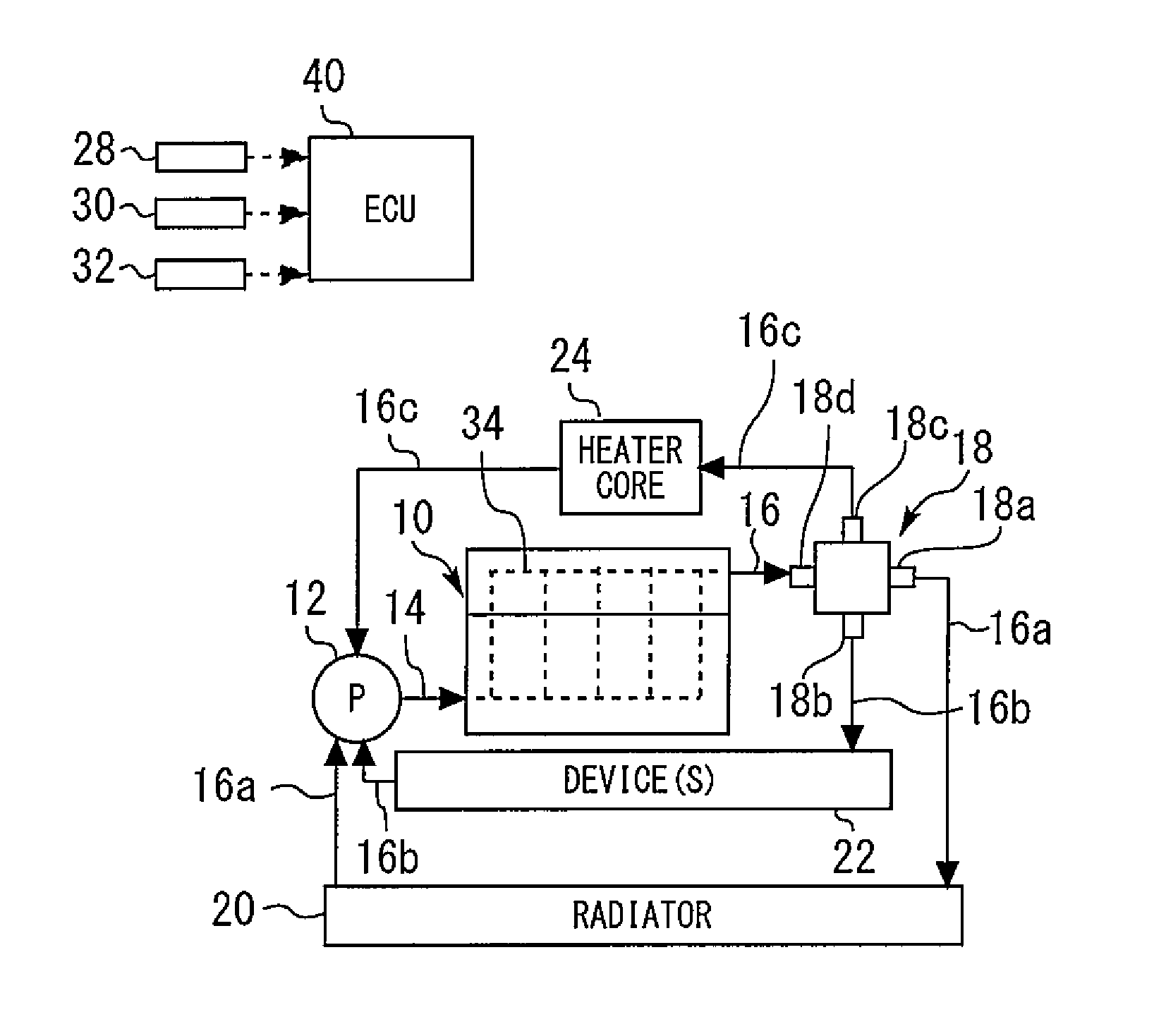
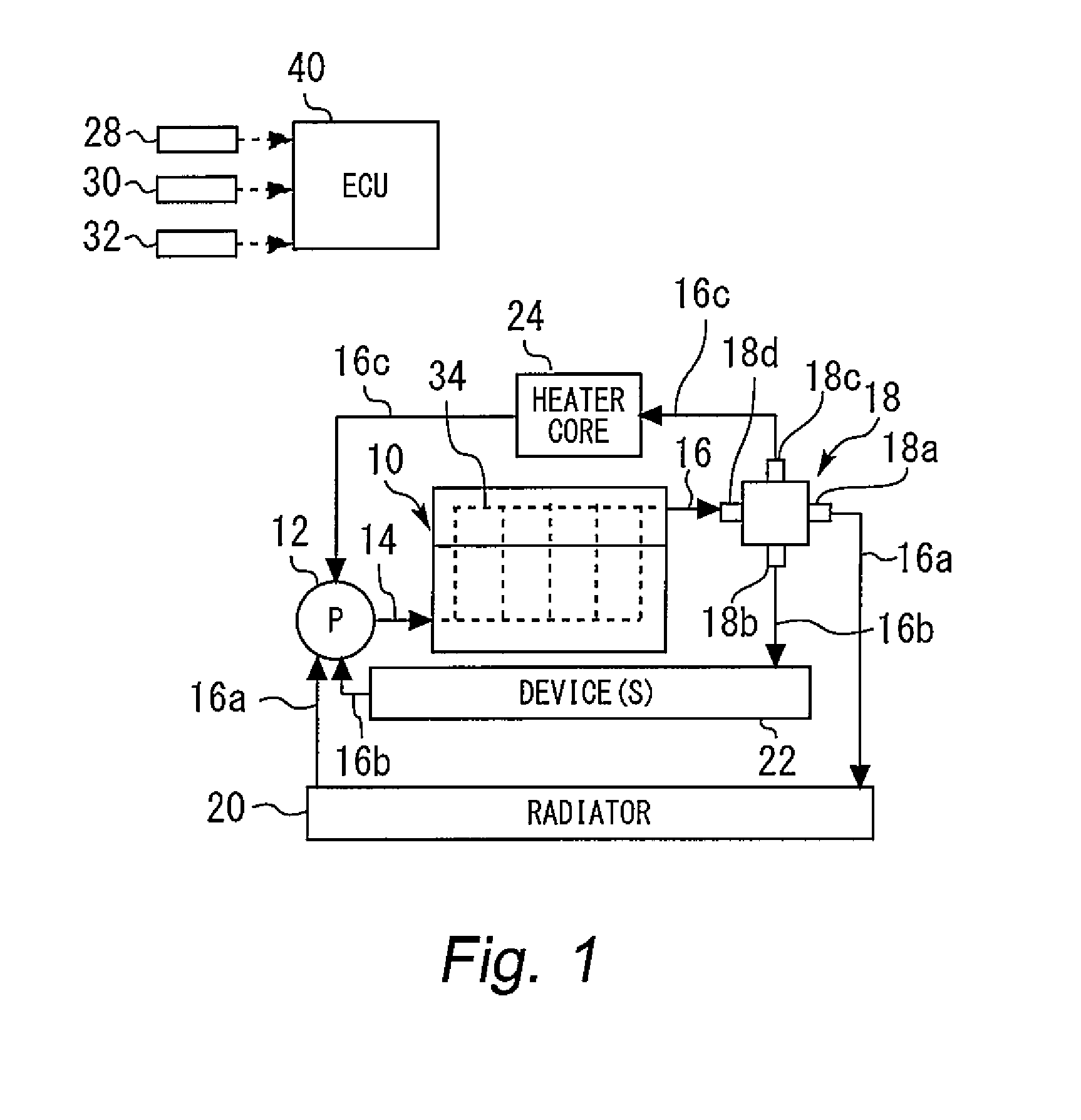
[0036]FIG. 1 is a view for explaining a configuration of a cooling device of an embodiment of the present invention. As shown in FIG. 1, the cooling device of the present embodiment includes an engine 10 as an internal combustion engine that is loaded on a vehicle. In a main body (a cylinder block and a cylinder head) of the internal combustion engine 10, a water jacket 34 is provided. Heat exchange is performed between a cooling medium (engine cooling water) that flows in the water jacket 34 and the engine 10.

[0037]The cooling medium which flows in the water jacket 34 is supplied from a mechanical type water pump 12. The water pump 12 includes an impeller (not illustrated) that delivers the cooling medium by rotation, and the impeller is configured to be rotationally driven by a rotational force of the engine 10.

[0038]An inlet portion of the water jacket 34 and...


PUM


Abstract

A cooling device includes a first cooling medium circuit for circulating a cooling medium that passes through a main body of an engine to a first heat exchanger, a second cooling medium circuit for circulating a cooling medium that passes through the main body to a second heat exchanger, a control valve that is commonly used in the first and second cooling medium circuits, and a control device. The control valve includes a rotatable rotor, and is configured such that a rotation range of the rotor includes a water stop section in which the circuits are both closed. The control device restricts output power of the engine in a period in which the rotation angle is in the water stop section, when the rotor rotates via the water stop section at an operating time of the control valve.

Description

CROSS-REFERENCE TO RELATED APPLICATION[0001]The present application claims priority to Japanese Patent Application No. 2015-149494 filed on Jul. 29, 2015, which is incorporated herein by reference in its entirety.TECHNICAL FIELD[0002]Embodiments of the present invention relate to a cooling device for an internal combustion engine.BACKGROUND[0003]For example, Japanese Patent Laid-Open No. 10-131753 discloses a cooling device including a cooling medium circuit in which a cooling medium that is caused to pass through both an engine and a radiator flows, a bypass channel that bypasses the radiator halfway in the cooling medium circuit, and a flow control valve that is provided in the bypass channel. In this device, the flow control valve is configured by a valve housing, and a rotary type rotor that is rotatably installed in the valve housing. By rotating the rotor, opening and closing states of the cooling medium circuit and the bypass channel can be controlled.[0004]Further, Japanese ...

Claims


Application Information

Patent Timeline
IPC IPC(8): F01P7/16F01P5/12F01P3/20
CPCF01P7/165F01P3/20F01P2060/08F01P2007/146F01P2037/00F01P5/12B60H1/06F02D41/0002F02D2250/18F02D41/04F01P2031/00F02D2250/26
Inventor WATANABE, HIROSHI
Owner TOYOTA JIDOSHA KK
Why Eureka
Try Eureka