
Systems and methods for quantitative phase imaging with partially coherent illumination

a technology of partially coherent illumination and phase imaging, applied in the field of quantitative phase imaging, can solve the problems of only providing qualitative information regarding the optical phase delay of a sample, and achieve the effect of accurate phase estimation

Inactive Publication Date: 2015-04-09
GEORGIA TECH RES CORP
View PDF2 Cites 17 Cited by
  • Summary
  • Abstract
  • Description
  • Claims
  • Application Information

AI Technical Summary

Benefits of technology

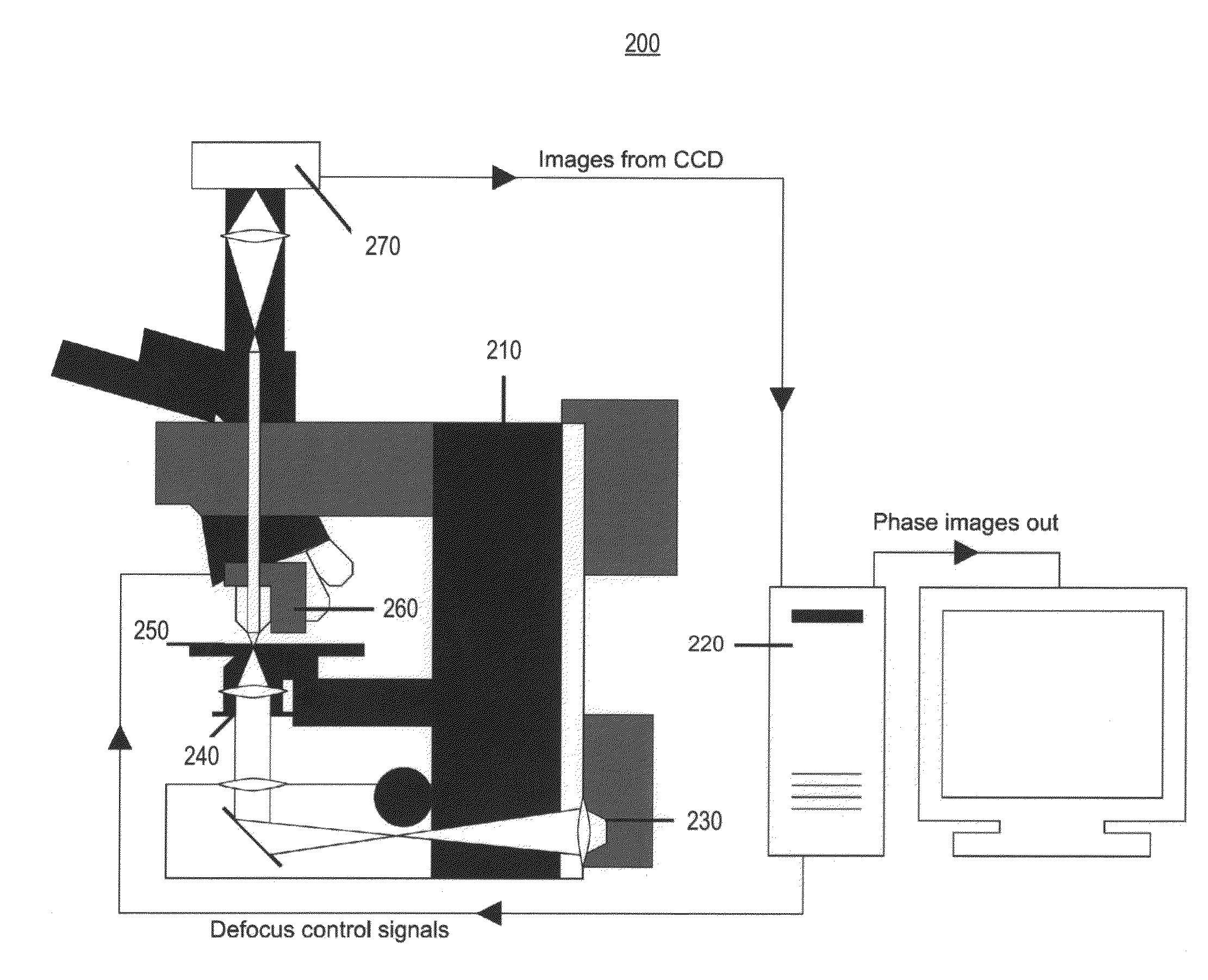
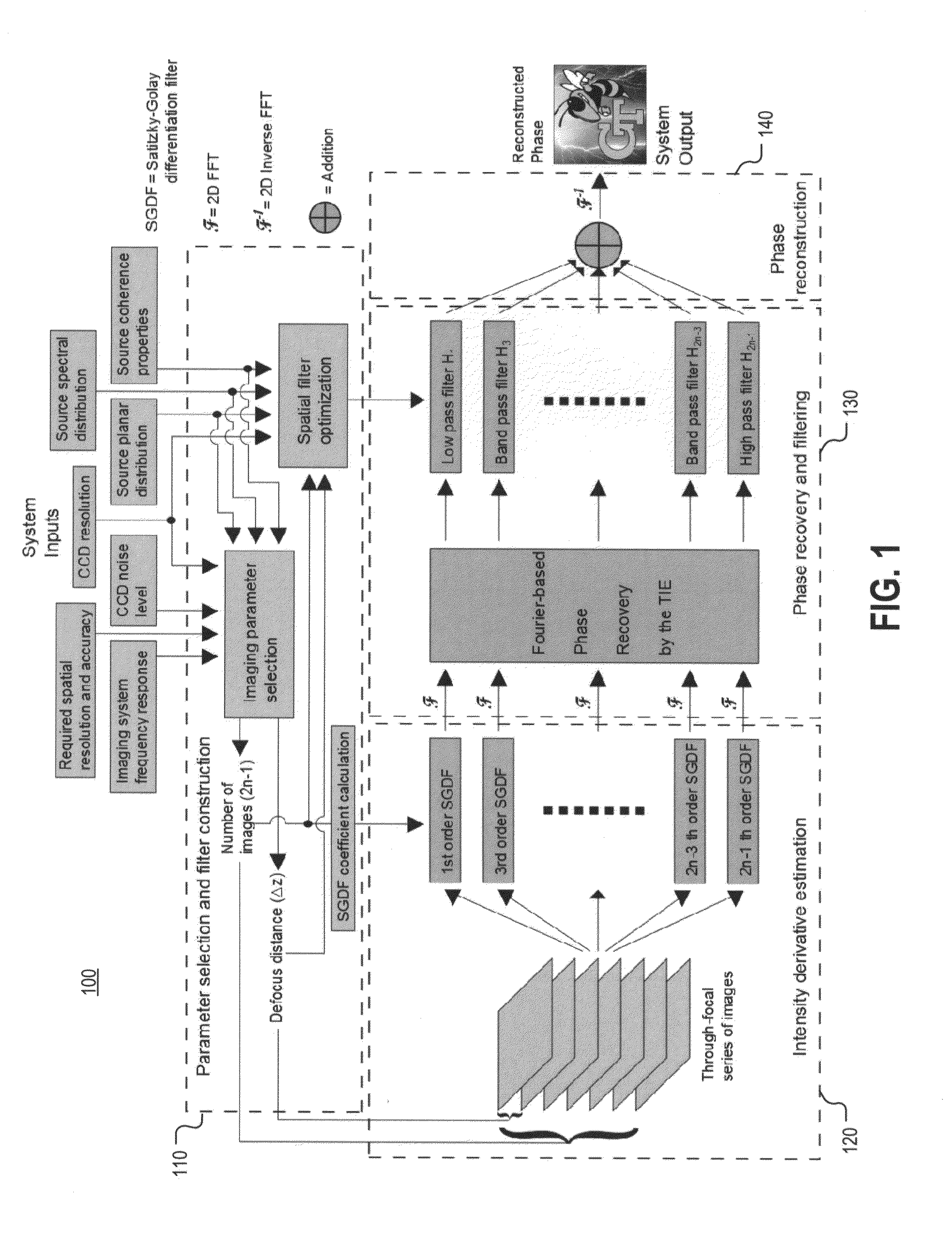
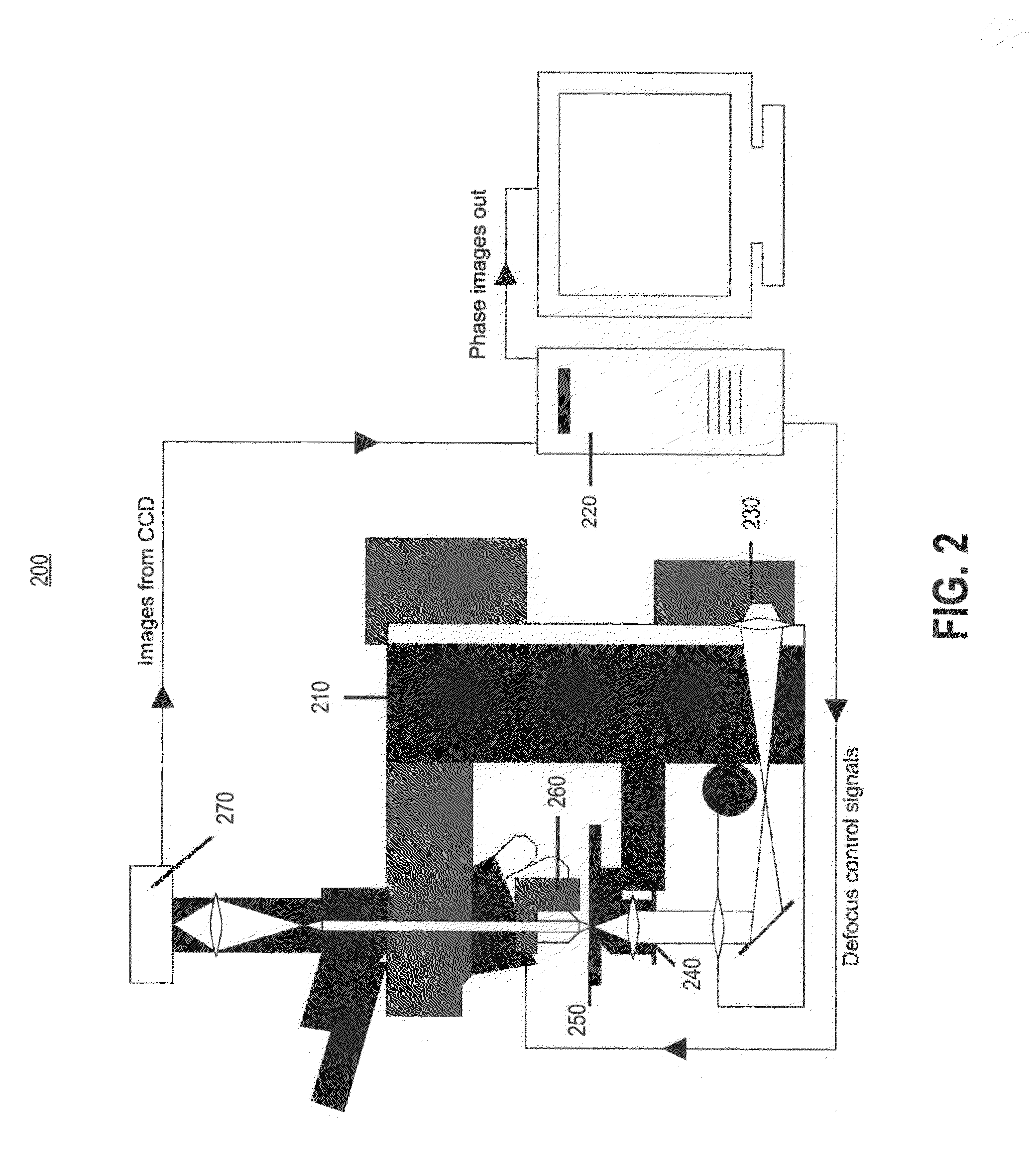
The patent text describes a new way to do quantitative phase imaging that overcomes limitations of conventional methods. This approach uses a multifilter approach with partially spatially coherent illumination, allowing for accurate phase imaging at different length scales. The system includes an optical setup, an image acquisition device, and a processor. The processor calculates derivatives of intensity, recovers the phase using a transport of intensity equation, filters the phase estimates, and combines them to form a final phase image. This new method provides a more accurate and reliable way to measure phase in a variety of applications.

Problems solved by technology

These methods, while useful, may only provide qualitative information regarding the optical phase delay of a sample.
Similarly, although fluorescence microscopy provides targeted structural information, using exogenous contrast agents such as fluorophores may alter the state of the sample and can result in death due to overexposure for biological samples.
Existing MFPI methods have only been derived for the spatially coherent cases [17, 21], and are not adapted to match the physics of partially coherent wave propagation, the regime for which the TIE method may be particularly well-suited.

Method used


Image

  • Systems and methods for quantitative phase imaging with partially coherent illumination
  • Systems and methods for quantitative phase imaging with partially coherent illumination
  • Systems and methods for quantitative phase imaging with partially coherent illumination

Examples


Embodiment Construction

[0047]The following detailed description is directed to systems and methods for quantitative phase imaging. Although exemplary embodiments of the present invention are explained in detail, it is to be understood that other embodiments are contemplated. Accordingly, it is not intended that the present invention is limited in its scope to the details of construction and arrangement of components set forth in the following description or illustrated in the drawings. The present invention is capable of other embodiments and of being practiced or carried out in various ways. Also, in describing the preferred embodiments, specific terminology will be resorted to for the sake of clarity.

[0048]It must also be noted that, as used in the specification and the appended claims, the singular forms “a,”“an” and “the” include plural referents unless the context clearly dictates otherwise.

[0049]Also, in describing the preferred embodiments, terminology will be resorted to for the sake of clarity. I...


PUM


Abstract

Systems and methods for quantitative phase imaging are disclosed. In one embodiment, a method includes acquiring a through-focal series of defocused images of an object illuminated with a partially coherent light source; calculating a plurality of estimates of longitudinal intensity derivatives for respective fittings of the series of defocused images; recovering a phase estimate for each respective estimate of the longitudinal intensity derivative by solving a transport of intensity (TIE) equation; filtering the recovered phase estimates to produce component parts of an overall phase estimate; and forming an overall phase image by addition of the filtered phase estimates.

Description

CROSS-REFERENCE TO RELATED APPLICATIONS[0001]This application claims priority to U.S. Provisional Patent Application No. 61 / 886,879, filed Oct. 4, 2013 and entitled “Method and Apparatus for Quantitative Phase Imaging in Partially Coherent Illumination,” the contents of which are fully incorporated herein by reference.[0002]Some references, which may include patents, patent applications, and various publications, are cited in a reference list and discussed in the disclosure provided herein. The citation and / or discussion of such references is provided merely to clarify the description of the present invention and is not an admission that any such reference is “prior art” to any aspects of the present invention described herein. All references cited and discussed in this specification are incorporated herein by reference in their entireties and to the same extent as if each reference was individually incorporated by reference. In terms of notation, hereinafter, “[n]” represents the n...

Claims


Application Information

Patent Timeline
IPC IPC(8): G01N21/45G01B9/02G06F17/14
CPCG01N21/45G06F17/142G01N2201/08G01N2021/458G01N2201/061G01B9/02041G01N21/41G02B21/14G02B21/367
Inventor GAYLORD, THOMAS K.JENKINS, MICAH H.LONG, JOSHUA M.
Owner GEORGIA TECH RES CORP
Learn More